by Graham Fry
Monitor robotic welding quality with WeldEye
April 11, 2019 in Articles
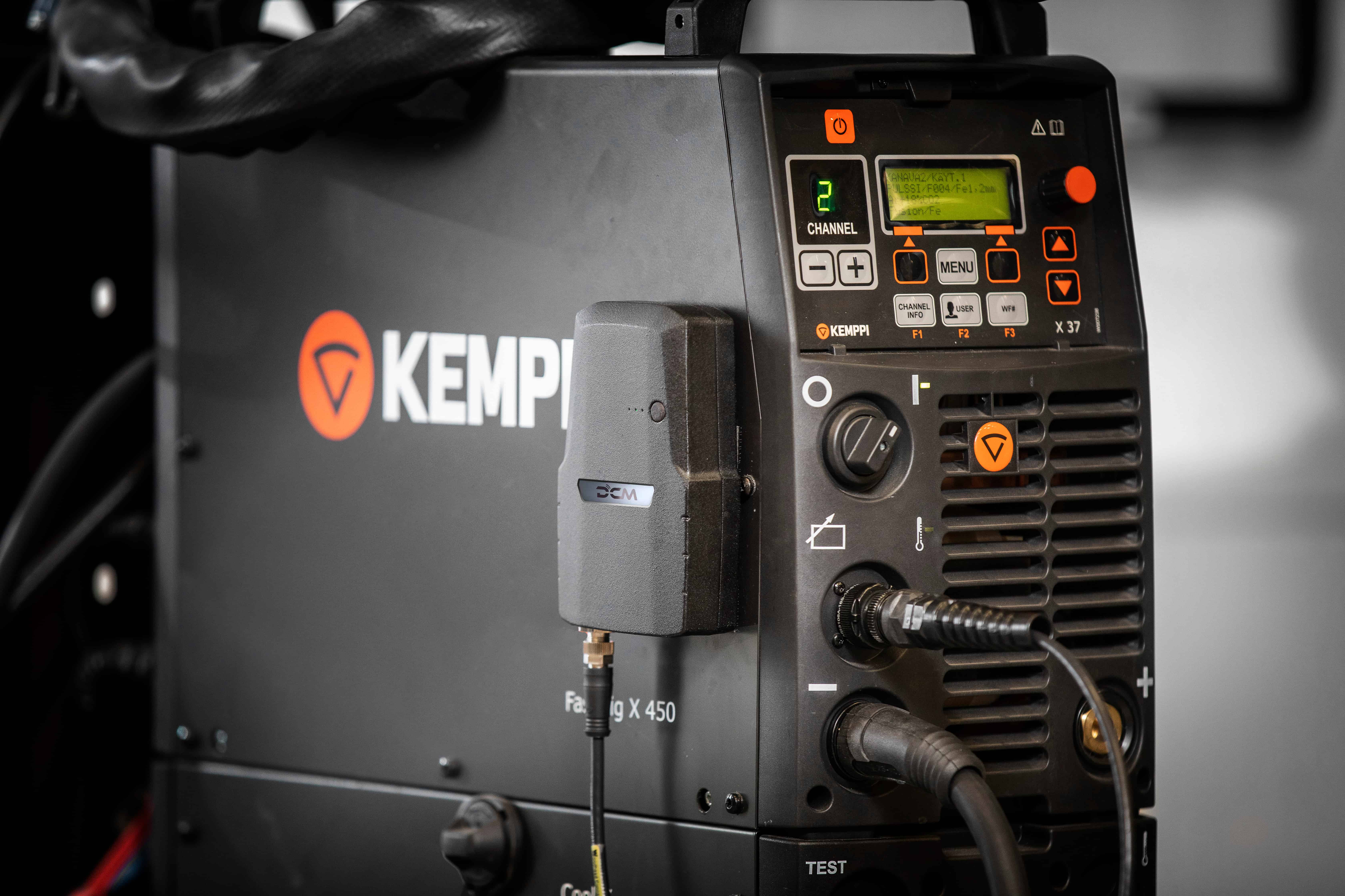
Universal welding management software WeldEye is now available for managing the quality of robotic welding. By collecting data from the welding robot and synchronizing it with weld lists in the cloud service, WeldEye provides an effortless way of monitoring robotic welding quality and its compliance with welding procedure specifications (WPS). In addition, the software ensures full traceability down to each weld and welded end product.
Data collection requires that the welding power source is connected to WeldEye’s Digital Connectivity Module. The device then transfers the data wirelessly to the software, where the information can be easily viewed and analyzed further.
In addition to the web browser-based user interface, the WeldEye mobile application can be used e.g. for real-time monitoring of welding parameters, operator identification, or selecting the filler wire material.
“With WeldEye you will know what has been welded, at which welding station, and when it happened. It also reports the used welding parameters, heat input, and any possible deviations in real time and with precision. The logic is based on identifiers, which help us track even a specific filler batch in welding production if it has been faulty,” says Vesa Tiilikka, Product Manager, Software at Kemppi Oy.
Integration with A7 MIG Welder
The development of the WeldEye software has been successfully piloted with Kemppi’s robotic welding system, A7 MIG Welder.
“All setups will be configured case-by-case according to the customer’s needs. If you have been looking for a robotic welding solution that can be monitored in terms of welding quality and traceability, I encourage you to contact us to see what we can do to help out,” says Artturi Salmela, Product Manager, Automation at Kemppi Oy.
WeldEye’s quality control functionalities are available when using WeldEye for Welding Quality Management, which includes the following software modules:
Welding Procedures
Personnel and Qualifications
Quality Management
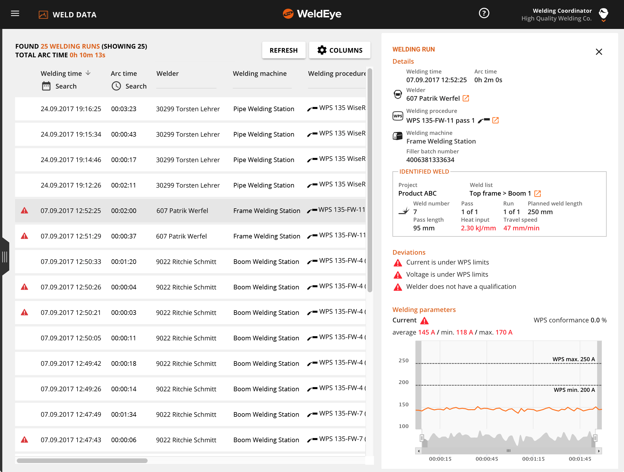
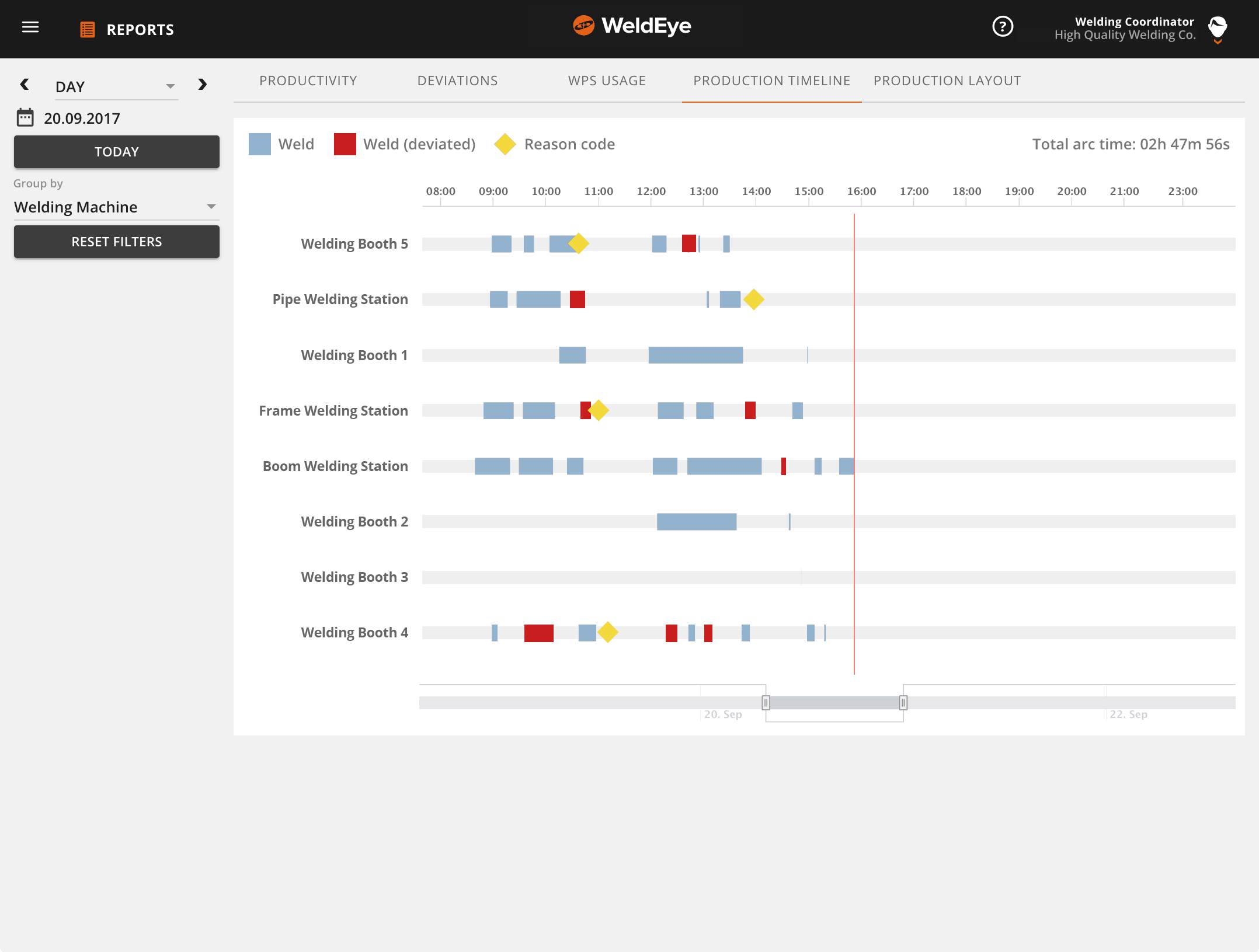
WeldEye collects data on arc-on time, welding deviations, and reason codes used to report non-welding activities.
Welding runs can be reviewed against the digitally collected, detailed welding parameter data and heat input calculations.
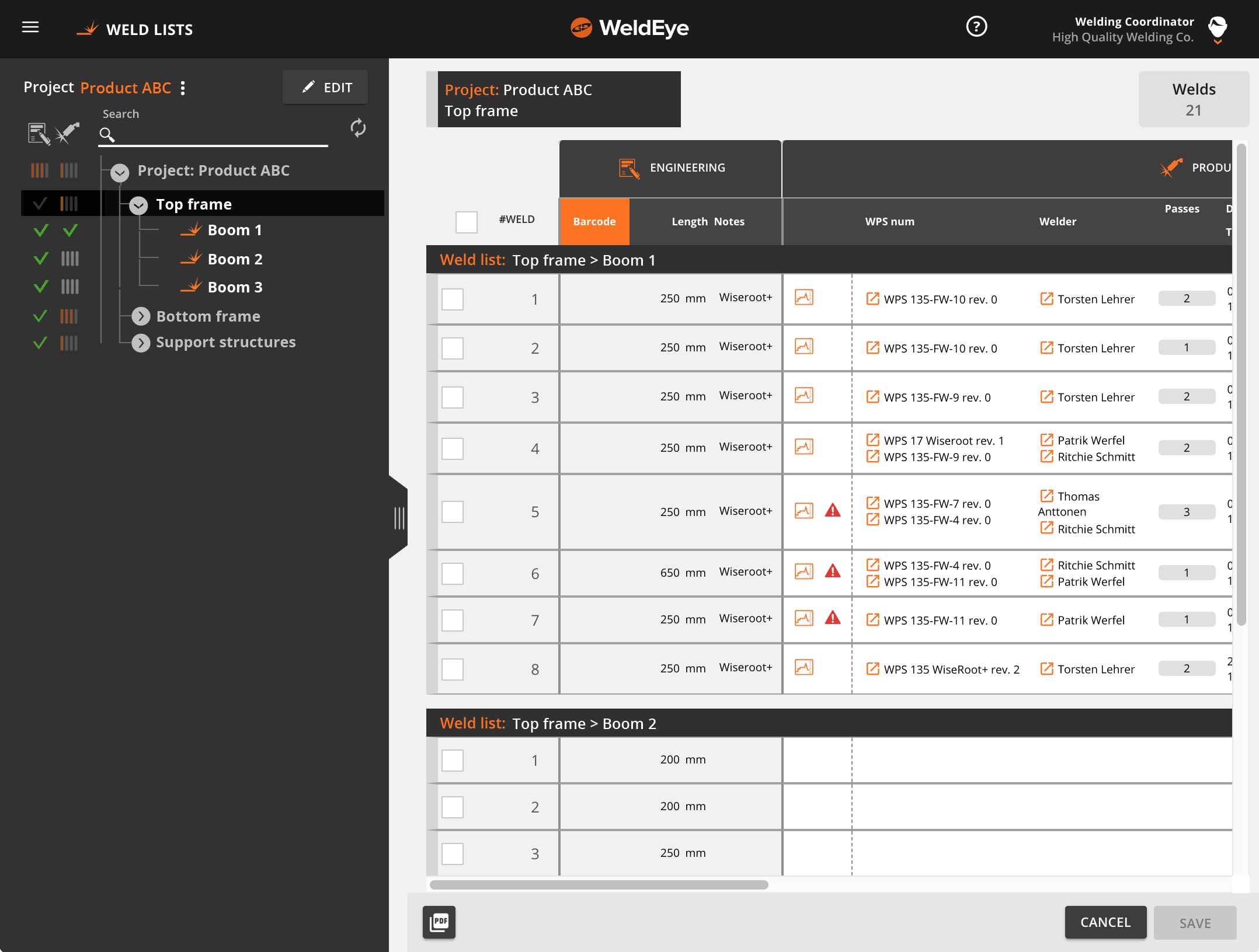
The data from the robot is synchronized with the weld lists and product structure in WeldEye, which enables full traceability down to each weld and welded end product.
For more information contact vesa.tiilikka@kemppi.com or artturi.salmela@kemppi.com
by Graham Fry
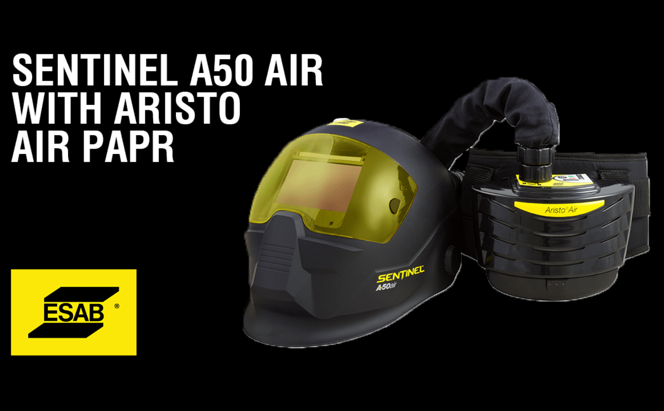
Sentinel A50 Air with Aristo PAPR
April 11, 2019 in Articles
The Aristo Air PAPR (Powered Air Purifying Respirator) system combined with the Sentinel A50 Air helmet, offers heavy-duty protection from welding fume and dust when welding, gouging & grinding. The unit features the latest in PCB Board technology, allowing the welder to adjust the air flow from 170 L/min to 210 L/min to suit the environment and application. This is highlighted by an LED airflow indicator on top of the unit. The Aristo Air is equipped with audio & visual blocked filter and low battery alarms, offering extra safety for the welder.
The strong physical construction of the Aristo Air, makes it extremely robust and suitable for all heavy-duty welding applications.
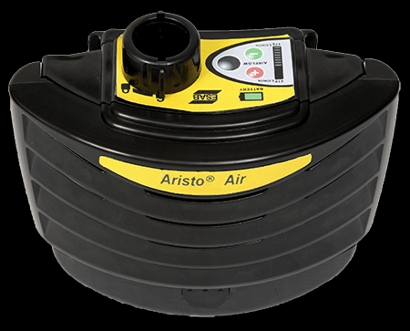
Aristo Air unit weighs only 1kg, allowing for longer wear time without the user getting fatigued and weighed down.
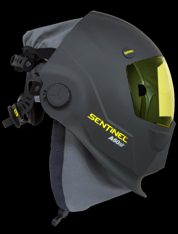
Sentinel A50 Air Helmet Features
- Crystal clear true colour visibility
- High impact revolutionary shell design
- Colour touch screen control panel
- Hard coated Anti-Scratch front cover lens (clear/amber)
- Halo™ Headgear: Ergonomic, infinitely-adjustable 5 point headgear provides extreme comfort and balance
- Externally activated Grind button. (Shade 3 grind mode)
- Low-profile design, central pivot point allows for maximum head clearance while the helmet is in the up position
- Low amperage TIG rated ≥2amp (DC) (AC)
- Memory – 8 location storage.
Years of welding have trained you to know exactly what you need in a hood: crucial comfort, large lens, and next-generation technology. Every special operation needs special equipment that gets the job done, and when it comes to your helmet, SENTINEL™ is worn by the best.
Aristo Air PAPR Features
- Li-Ion battery pack (up to 8hr duration @ 210L/min)
- P3 filter and pre-filter
- Audio/visual blocked filter and low battery alarms
- LED air flow indicator
- International intelligent charger (interchangeable pins)
- Battery charge LED indicator
The strong physical construction of the Aristo® Air, makes it extremely robust and suitable for all heavy-duty welding applications.
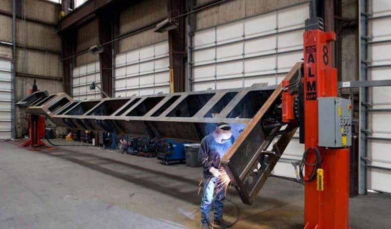
Suitable For
- Plasma Cutting
- Oxy-Fuel Cutting
- SMAW/MMA (Stick)
- GTAW (TIG – Tungsten Inert Gas )
- GMAW (MIG/MAG – Metal Inert Gas / Metal Active Gas)
- Grinding
Find your nearest distributor to order your system now!
by Graham Fry
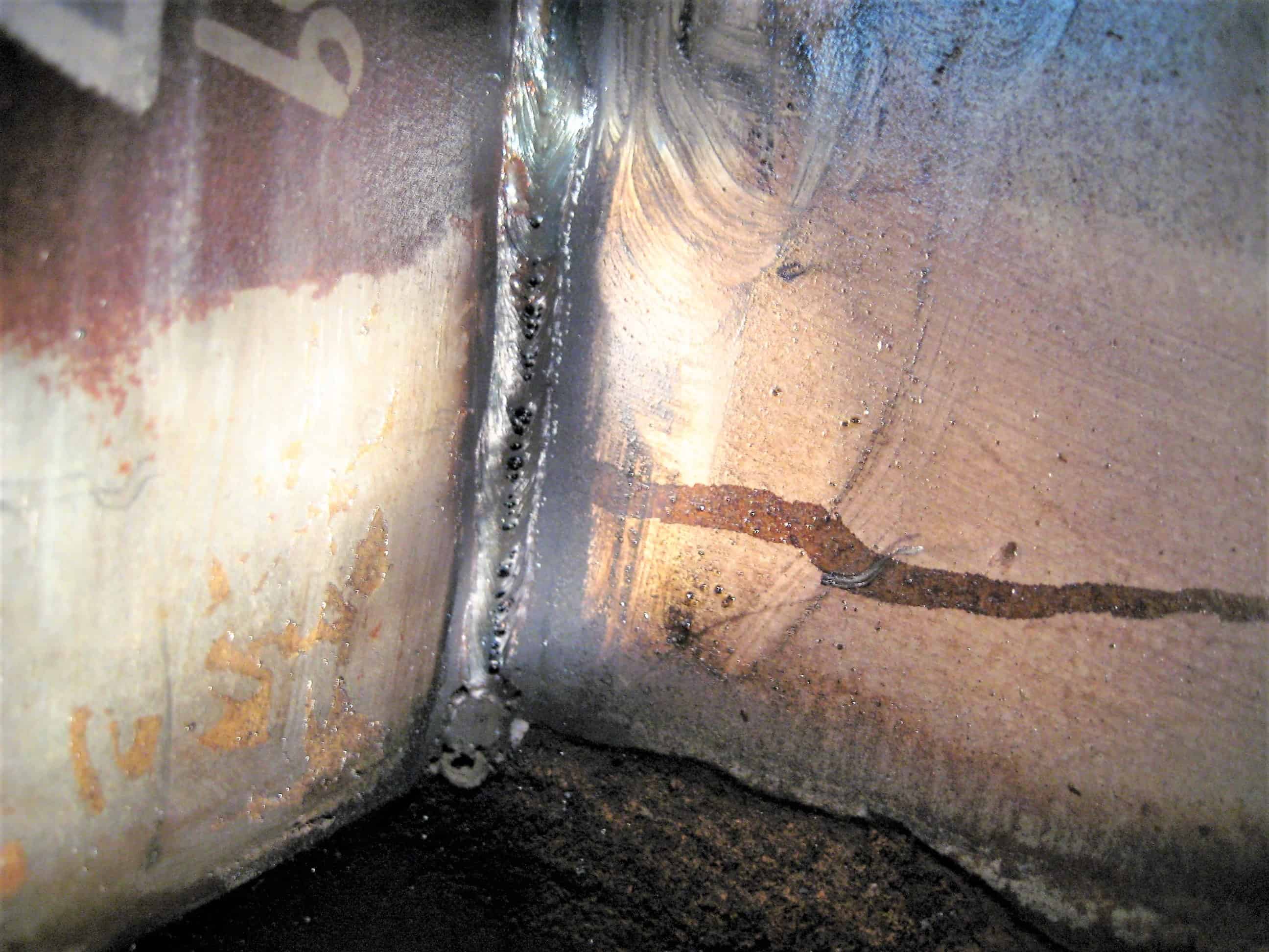
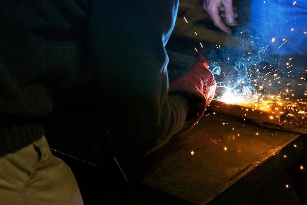
The Real Cost of Missed or Defective Welds
April 11, 2019 in Articles
The goal of any Australian welding and fabrication company is to create quality products for their customers, while also managing costs and maintaining the desired levels of productivity and quality.
Missed or defective welds can severely affect costs, productivity and quality levels of the company and defects in the welds could also lead to potential safety issues and a loss of company income.
Being able to clearly identify problems early in welding and fabrication activities is crucial — and welding information management systems can help
Detecting problems early
Given that overseas competition can make life tough for Australian fabricators; fabricating quality parts, maintaining high productivity levels all the while seeking ways to reduce costs all become critical factors.
It is therefore important for fabricators and management to consider some of the following questions:
- Is the design overly complex, making it more prone to missed or defective welds?
- Are we able to complete visual inspection – ensuring that all welds are in place and compliant?
- How much risk is our company willing to take that the visual inspection is accurate?
- What are the long-term consequences if a part fails?
In every case, missed or defective welds will lead to cost implications for the company. They could also pose significant safety hazards and even lead to serious personal injury for a site worker or member of the public. The cost implications if a defective weld can result in a failure in the field or in an insurance claim. We all recently heard on the news of the Victorian road sign that fell from its support structure and onto oncoming traffic. So, the earlier in the welding process that companies identify mistakes, the less costly it will be to correct the problem. Generally, the costs of welding fabrication can be identified as:
- Labour: 85%
- Welding consumables: 6%
- Raw materials: 4%
- Gas shielding: 3%
- Utilities: 2%
However, these costs can all go up significantly when a weld is missed or defective.
The methods of reducing these potential cost impacts can be completed during the various stages of the fabrication cycle.
Stage one: welding booth
At this stage, identifying a missed or defective weld is the ideal scenario. A welding supervisor or the welders him/her self can usually spot the missed weld easily and correct the issue. This action would be the most cost-effective method.
Weld defects may pose a slightly more difficult problem as they may require the removal of the weld and its rework. Rework costs would typically be two or three times that of the original fabrication.
Stage two: the shop floor
Fabrications on the larger shop floor and that come together from a series of sub-assembly parts can be visually inspected, with defective welds that are identified or welds that have been missed can be returned to the welding booth if the boilermaker/welder does not have the equipment or qualifications to make adjustments.
If the sub-assembly is large, the company may accumulate downtime for moving it. This will inevitably lead to lost productivity and unnecessary costs. Returning a part to the welding booth could also lead to a welder waiting on a part.
The result is a bottleneck that affects the company’s throughput and profitability.
Stage three: the paint shop
At this stage, and after painting has been completed, the rectification of missed or defective welds that are identified will mean the company will need to remove the paint and return it to the shop floor.
These failures will cause the company to amass extra labour and rework cost, but also for the paint itself. For larger components which require painting all at once, these costs could be significant.
Stage four: final fabrication assembly or site assembly
If a company identifies missed or defective welds in this stage, it will require disassembling the part, removing paint and returning the part to be completely fabricated again. By starting the entire welding process over, costs continue to escalate due to both downtime and labour.
If defects are identified on site, the company might be able to deploy mobile welding equipment to rectify the problem. Correcting a missed or defective weld in this way requires additional labour for an employee dedicated to this site welding, with potential costs of having to use a site welding process (MMAW) and a possible field weld repair procedure. There may also be site induction costs plus the inefficient use of a shop welder. Having mobile welding equipment also requires a capital investment for equipment that is only used periodically.
Stage five: customer identification
If a customer inspection identifies a missed or defective weld, a company could accumulate costs to remove the product and deliver a new one.
In the case of a piece of a heavy fabrication, these costs could be substantial and can lead to warranty claims in addition to having to remove and replace the item. The company’s reputation would be at risk, especially if the problem is reoccurring and becomes known throughout the industry. In some cases, tier one companies who supply welded fabrications could potentially lose job contracts if they generate a poor track record for missed and/or defective welds.
Stage six: insurance claim
Property damage or bodily injury is the most significant consequence of a missed or defective weld. This threat to safety is a very real concern and one that far exceeds the financial ramifications a company could experience as a result. Yet, there are still those financial concerns. Insurance claims can generate significant expenses at this point. Negative — and potentially, permanent — damage to the company’s brand reputation is also possible and could lead to future loss of business and profits. Again, these effects are always secondary to a catastrophic event, but companies must consider them as due course of operating a successful business.
Solution options
For some companies, standard quality control inspections may be enough to protect against missed or defective welds. For example, welding operations with smaller, less complex parts may be easier to evaluate on an ongoing basis. Companies with larger and more complicated welding applications or parts, however, may find the need to implement quality checks throughout the welding process, leading to higher labour costs. Such operations could benefit from alternative other means of quality and cost control.
Advanced welding information management systems are one such option. These systems electronically gather weld data to help companies drive quality and productivity improvements in the welding operation. Among other features, they also provide real-time feedback to the welding operator to help prevent missed or defective welds. Using a human-machine interface (HMI), the system guides the welder through the correct weld sequence and weld placement using visual cues on screen (usually a ruggedised PC monitor), counting each weld as it is completed. Welders must finish each weld correctly and in order before proceeding to the next one.
Advanced welding information management systems also monitor welding outputs to ensure that the welding operator is welding within the weld procedure to create a quality weld. They are capable of tracking multiple factors, including:
- Amperage and voltage
- Gas flow
- Wire feed speed
- Weld duration
Companies can program an advanced welding information management system to respond accordingly if a welder welds outside of the procedure ranges. The system can provide a simple alert or it can disable the welding gun entirely until the welding supervisor or engineer is able to identify the problem and offer a solution.
Many equipment manufacturers can offer welding information management systems. By choosing to monitor weld sequence and parameters, a company that has chosen to invest in such equipment can reduce or prevent productivity loss, product quality failure, and damage to its brand image.
When a company considers that upfront cost compared to the long-term benefits and savings of these systems, the investment starts to make good business sense.
by Graham Fry
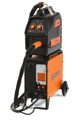
Kemppi releases new, tough and cost-effective X3 MIG Welder for MIG welding and carbon arc gouging
March 19, 2019 in Articles, Equipment, Welding
Leading international welding equipment manufacturer, Kemppi, has launched the new Kemppi X3 MIG family, an evolution of its popular HiArc MIG range. The X3 is a basic and cost-effective MIG alternative to Kemppi’s premium FastMig welding family, but with a high duty cycle and robust design is suitable for the tough and demanding conditions found in the metal fabrication industry.
Available as a gas-cooled MIG/MAG welding package with carbon arc gouging, the X3 MIG Welder delivers excellent performance with up to 500 amperes at a 60% duty cycle. The machine is equipped with a wire feeder for 300mm wire spools and accepts wire diameters from 0.8 to 1.6mm, and with cored wires up to 2.0mm.
Benefits
It also offers outstanding welding control to deliver quality welds. The MIG/MAG process of the X3 MIG Welder has been carefully tuned at the Kemppi welding lab to give the arc excellent stability. This makes the arc easy to manage and minimises spatter, even when using inexpensive CO2 shielding gas. With less spatter, the need for post-weld grinding is reduced, and welders can use more of their time for productive welding.
In addition, the machine has a range of functions that fine-tune the start and end of welds, improve the quality of the weld and help boost productivity. These include Crater Fill, Burn Back, Hot Stop, Soft Start, Hard Ignition and Creep Start.
Plus, the machine is also very energy efficient. Kemppi is the number one pioneer in welding inverter technology, and the X3 MIG Welder uses the latest IGTB inverter technology to reduce its energy usage and minimise costs.
Features
A practical, no-nonsense machine for the professional welder, the Kemppi X3 MIG Welder is both robust and rugged. The system’s wire-feeder features a fully enclosed and impact resistant dual-skin cabinet to protect the wire spool and feed mechanism so that it can withstand rough handling.
Compact and lightweight, the machine is easy to move between work sites. Ergonomically positioned handles ensure easy maneuvering of the machine. Plus, carriage and wheel set options are available to further facilitate easy transportation.
The X3 MIG Welder is simple to operate. The control panel communicates with the welder entirely by symbols. To select the basic features, the welder just pushes the appropriate buttons and makes selections with the adjustment knob. During welding, wire feeder control knobs are used to adjust the wire feed speed and voltage. What’s more, the X3 MIG Welder automatically takes care of adjusting the amperage according to wire feed speed in order to create top quality welds.
‘The X3 MIG Welder contains all you need for basic welding work at a very competitive price,’ says David Green, Managing Director, Kemppi Australia. ‘It’s the perfect companion for all professional welders out there, who just want to get the job done ‒ quickly and without compromising quality.’
For more information on the new X3 MIG Welder call Kemppi Australia on (02) 8785 2000 or email sales.au@kemppi.com
by Graham Fry
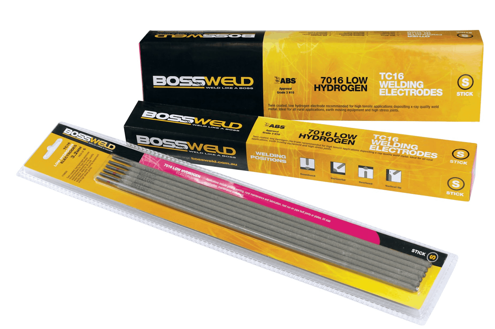
Introducing the Bossweld TC16 Low Hydrogen Twin Coated Electrodes
March 18, 2019 in Articles
Dynaweld, the welding supply experts, are delighted to announce the launch of the Bossweld TC16 hydrogen controlled, twin coated electrodes.
The Bossweld TC16 hydrogen controlled, twin coated electrodes have been through a rigorous schedule of R&D and testing to produce an electrode that is the equivalent of the market leading 7016 twin coat electrode.
Get your FREE sample pack!
As an Australian Welding Institute member exclusive, Dynaweld is offering a free sample pack to all members.
Follow this link for your free sample or to find out more about the Bossweld TC16 hydrogen controlled, twin coated electrodes.
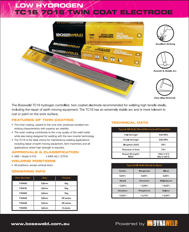
The ideal choice for all applications where high strength is required
Designed for welding high tensile steels, the TC16 electrodes are ideal for rural maintenance, fabrication and repair of farm machinery.
Other applications include general welding and maintenance welding jobs such as repair of earth moving equipment, root run on pipe butt joints or plates.
And because the TC16 has an extremely stable arc it is more tolerant to rust or paint on the work surface than other electrodes.
The advantages of twin coat
The inner coating of the TC16 electrodes contains the ionising and conducting ingredients that enable a strong and stable arc to be concentrated around the wire.
This inner coating provides excellent arc striking characteristics and superior arc stability.
The outer coating contains the shielding and slag-forming elements and is non-conductive.
It contributes to the x-ray quality weld metal and it is also designed for welding with the new inverter technology.
Many features and benefits
Enjoy the many features and benefits of these easy-to-use low hydrogen twin coat electrodes, including:
- Excellent arc striking characteristics
- Smooth and stable arc
- Easy slag removal
- Tolerance to rust or paint on the work surface
- Delivery of x-ray quality meld metal
The Bossweld TC16 hydrogen controlled, twin coated electrodes are suitable for inverter welding and all positional welding (except vertical down).
And they are guaranteed to do the job, with ABS Approval – Grade 3 H10.
by Graham Fry
Mastering GTAW of anodized aluminium
February 18, 2019 in Articles
Performing gas tungsten arc welding (GTAW) on anodized aluminium is a bit like trying to poke a hole in a sheet of ice without disturbing the water underneath. In this case, the ice is the hard layer of oxide created by the anodisation process and the water is the soft aluminium underneath.
Anodized aluminium is simply standard aluminium that has been treated to produce a thick layer of oxides on its surface. The aluminium base is a very soft material and melts at approximately 590 °C, but the oxide layer is extremely hard (some types approach the hardness of diamonds) and melts at 1980°C. The difficulty in welding anodized aluminium lies in removing the oxide layer without burning through the aluminium base.
GTAW on anodized aluminium requires different equipment, preparation, and technique than on standard aluminium. Its corrosion resistance makes it ideal for boating accessories, such as this tuna tower, that are exposed to high-salinity environments.
Interestingly, it is these properties of the oxide layer that make anodized aluminium a useful material in the first place. It is relatively inexpensive, visually appealing, lightweight, and corrosion-resistant, making it suitable for high-salinity environments, such as coastal areas.
Without any treatment, aluminium naturally forms a very thin layer of oxides. The process of anodizing aluminium uses an electrolytic chemical application, usually with sulphuric acid, to create a layer of oxides several times thicker than would naturally form —0.005 to 0.025 mm thick.
Anodized aluminium Types
The four types of anodized aluminium are standard, bright-finish, coloured, and hardened.
Bright-finish anodized aluminium can be visually distinguished from standard anodized aluminium by its shiny, chrome-like finish. This type of material has a thicker layer of oxides than standard anodized aluminium, making it more difficult to GTAW, and is used primarily for cosmetic reasons.
Coloured anodized aluminium is also used for cosmetic purposes. This material uses dyes in the anodisation process, which allow the material to take on different hues, but also introduce potential contaminants into the weld.
Hardened anodized aluminium is almost as hard as a diamond and is very difficult to weld. This type of material is usually used only in highly specialized industrial applications.
Bright-finish, coloured, and standard anodized aluminium’s all use much the same equipment, preparation, and technique as standard aluminium, but they have some unique requirements in order to be welded successfully.
Selecting the Right Equipment
Selecting the right equipment is the first step in welding anodized aluminium successfully. Equipment unique to the process includes a torch with a fingertip control and a 5356-class filler metal. An air-cooled torch is suitable for less than 200 amps, but a water-cooled torch should be used for applications requiring more amperage.
Like standard aluminium, anodized aluminium also requires a 100 percent argon shielding gas or an argon/helium mixture and a 2 percent ceriated (orange stripe) or thoriated (red stripe) tungsten. [Note: Thorium is radioactive. Always follow the manufacturer’s warnings, instructions, and the Material Safety Data Sheet for its use.] Pure tungsten (green stripe) also can be used, but only up to about 70 percent the amperage of ceriated or thoriated tungsten.
When preparing the tungsten, grind it to the same type of point that you would when welding steel or stainless steel. Be sure to regrind the tip when it rounds off and causes the arc to become unstable. Repeat this process as necessary.
A power source capable of alternating current (AC) is also necessary because the electrode-positive portion of the current cycle breaks apart the oxide layer.
Although some traditional transformer-based GTAW power sources are capable of successfully welding anodized aluminium, an inverter is highly recommended for its balance and frequency controls.
Balance control allows you to adjust how long the current spends in each part of the AC cycle. For example, a balance control set to 30/70 means that the current spends 30 percent of its cycle in electrode-positive, cleaning the oxide layer from the base material, and 70 percent in electrode-negative, directing the electrical energy into the weld joint and joining the two pieces of material.
Your experience and skill will determine how you set the balance control. A more skilled welder often can use a higher percentage of electrode-negative (80 to 90 percent) in order to work faster.
The frequency control function available on inverter units allows you to determine the length of time that it takes the unit to complete one full current cycle (the combined time spent in electrode-positive and electrode-negative.)
Transformer-based power sources produce an output of 60 Hz, which is the same frequency that comes from a standard outlet. Inverters, however, are able to adjust the frequency from 20 to 400 Hz. For anodized aluminium, a frequency of about 160 to 200 Hz generally produces the best results. The frequency produces a narrower arc cone and, consequently, a narrower weld bead and HAZ. The strength of the weld increases by reducing the area of the base material exposed to the heat of the arc. A narrower weld bead reduces the time and filler metal needed to make the weld.
An inverter machine also eliminates the need for a backhanding technique. Backhanding, also known as backing around the weld, involves making two passes on each weld joint—one pass going forward to clean off the oxide layer and then reversing direction to add filler metal to the area just cleaned. In addition to doubling the time it takes to weld the joint, backhanding requires the workpiece to be heated twice, and this can reduce the strength of the weld.
Material Preparation
Properly preparing the material is critical to ensuring strong and cosmetically appealing welds on anodized aluminium.
The material should be at room temperature for at least an hour before welding, otherwise condensation can form within the aluminium and react with the argon shielding gas, creating porosity and a black, sooty appearance on the weld.
Cleaning any residue, dirt, or other foreign material from the base metal and filler metal with a clean cloth prior to welding helps prevent weld defects such as porosity, inclusions, and lack of fusion.
Although the electrode-positive portion of the AC cycle helps remove the oxide layer that builds up on aluminium, you may want to use a dedicated stainless steel brush to manually clean the material before welding. Using this brush for other purposes will introduce foreign contaminants to the weld joint and compromise the weld’s structural integrity. An oxide layer begins to form immediately after brushing, so it is also necessary to rebrush a piece that sits for an extended amount of time without being welded.
Technique
Anodized aluminium requires a technique known as bumping, which is a way to remove the thick oxide layer without putting too much heat into the weld pool. Because it uses a fingertip control switch, a foot pedal is unnecessary for this technique.
Bumping involves very briefly starting an arc using the finger control switch, adding the filler metal, extinguishing the arc, moving down the weld joint about 1.6mm, and repeating the process. Turning the fingertip switch off gives the weld pool a moment to cool and solidify before you reintroduce the heat with a new arc.
Although easily described, bumping is one of the more difficult GTAW techniques to master. A proficient operator typically can reach a travel speed of about an inch every 30 to 40 seconds.
The amperage range you use will depend on your skill, with a beginner to intermediate welder using around 180 to 190 amps, and a highly skilled welder around 230 amps.
The thickness of the material will require you to adjust the travel speed—thin material requires a faster travel speed than thicker material—but the amperage range typically remains the same regardless of material thickness.
At those amperage levels, a filler metal of 3.2mm diameter should be used. Anything smaller will melt off before it gets to the weld pool. It is also important when adding the filler metal to insert it at the leading edge of the weld pool while the arc is live and to remove it before extinguishing the arc, so that the filler metal doesn’t become trapped in the weld pool as it cools.
The distance between the end of the filler metal and the weld should be no more than the diameter of the torch cup.
Although anodized aluminium certainly poses some unique challenges, its weight, low cost, and resistance to corrosion make it the best option for many applications and environments. Following this advice should help you overcome the difficulties associated with this material and realize its potential benefits.
Copyright © PRACTICAL WELDING TODAY
Written by JACK FULCER
by Graham Fry
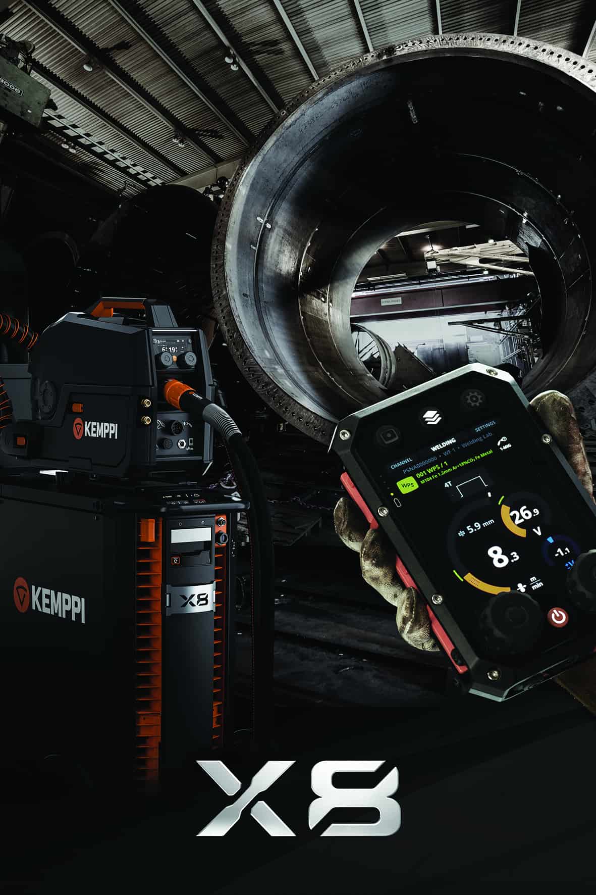
Kemppi redefines extreme industrial welding with the X8 MIG Welder
February 18, 2019 in Articles
Leading international welding equipment manufacturer, Kemppi, has unveiled its new Kemppi X8 MIG Welder for extreme industrial welding – the ultimate choice for demanding welding. The X8 MIG Welder is a multi-process system for synergic and pulsed MIG/MAG welding, MMA welding, MIG brazing, cladding and gouging. It delivers extreme power and accuracy using the most common electrical network voltages. Developed, designed and made in Finland, the X8 MIG Welder ensures the very best in performance. This intelligent equipment provides users with extremely precise control of the arc, high-duty welding performance up to 600 A, upgradable power sources, digital WPS and native connectivity with WeldEye welding management software so that they can perform, control and manage welding production in a way that was not possible before.
Designed with precision, welding efficiency and quality in mind, the X8 MIG Welder’s welding arc characteristics deliver enhanced performance – particularly on austenitic stainless steels, aluminium and advanced high-strength steels. To improve quality control and eliminate the need for printed WPS, the X8 MIG Welder features an integrated digital WPS (dWPS) function. By connecting the X8 to the WeldEye cloud service, welders can search, view and activate WPS via the Control Pad display and automatically use the right parameters during welding.
Fast and accurate, the digital WPS function ensures quality control, and helps saves time and money during welding production. The X8 MIG Welder also features a sophisticated Control Pad. In addition to allowing the welder to access and view digital WPS, the Control Pad also lets welders set and adjust parameters to control welding. The device can also be used to collect fabrication information to verify that the weld meets WPSs and analyse welding productivity based on arc time and tracking. Ergonomically designed, the welding gun of the X8 MIG Welder has been shaped for maximum comfort. The hand grip, mobility and stability of the gun have been optimised to meet the most demanding welding tasks. Plus, the innovatively designed wire feeder ensures safe and ergonomic loading of the filler wire spool.
Easy to set up and configure when compared to standard welding equipment, the X8 MIG Welder is ideal for use in a range of industrial applications including on oil rigs, process pipelines, and pressure vessels and boilers.
‘Smart, powerful and robust, the X8 MIG Welder adapts easily to any welding environment and meets even the most extreme expectations of industrial welding,’ said David Green, Managing Director, Kemppi Australia.
For more information on the new X8 MIG Welder call Kemppi Australia on (02) 8785 2000 or email sales.au@kemppi.com
by Graham Fry
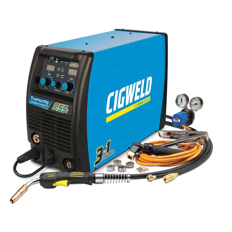
Launching the NEW Transmig 255i!
February 15, 2019 in Articles
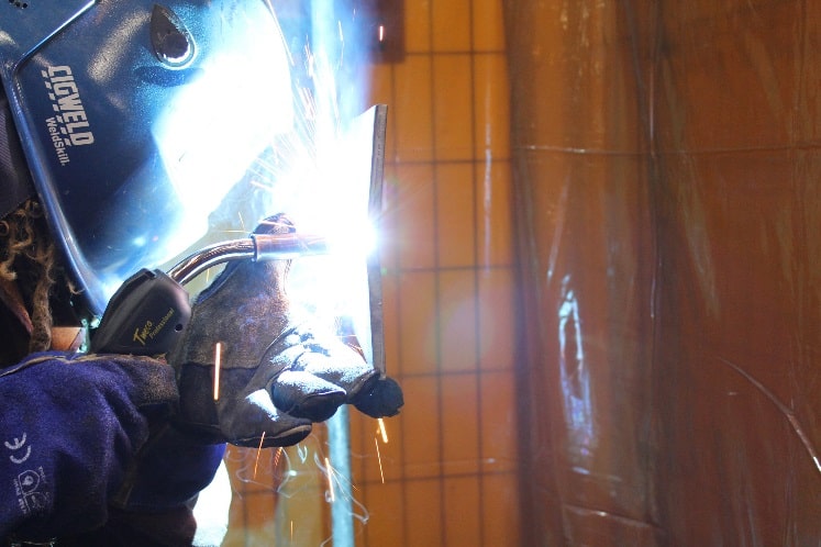
It is with great excitement that CIGWELD/ESAB announces the launch of the new Transmig 255i! These units will be available in early February with pre-orders being accepted NOW!
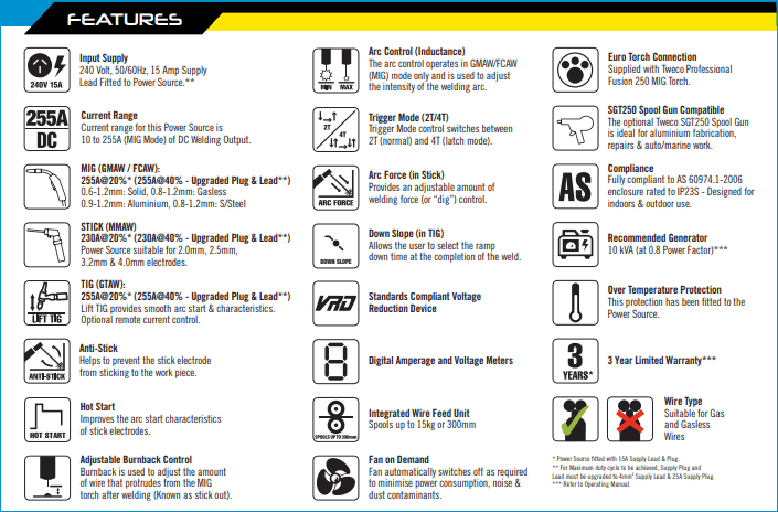
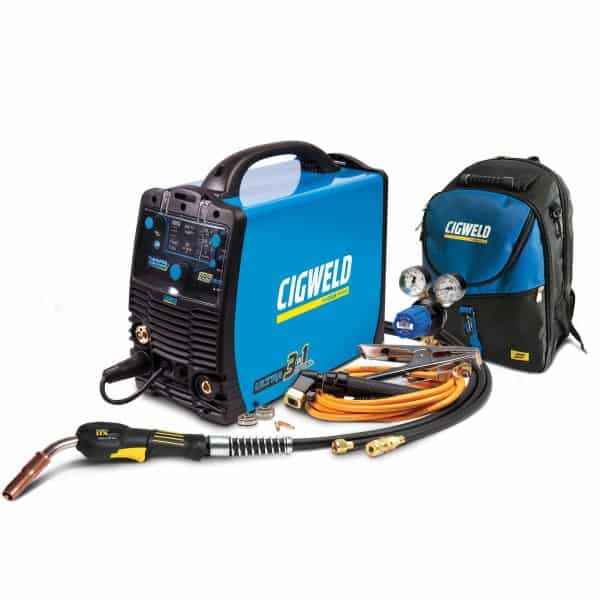
The Transmig 255i is a compact self-contained single phase multi-process welding inverter, capable of welding MIG (GMAW/FCAW), Stick (MMAW) and Lift TIG (GTAW). Ideal for welding plate thicknesses between 0.8mm and 12mm with a range of wires from 0.6mm – 1.2mm (solid).
The Transmig 255i is ideal for onsite repairs and maintenance, medium industrial workshops, car panel repairs or serious welders that want a single phase inverter they can plug in and use around their own home workshop.
Coming standard with a 15amp plug, this machine can easily be upgraded to a 25amp plug and 4mm2 supply lead to increase the duty cycle to an impressive 255A @ 40%.
The Transmig 255i is equipped with an integrated wire feed unit that fits 300mm spools, 2T/4T, Down Slope (in TIG), adjustable Arc Force (in Stick), VRD (which is applicable in stick mode), PFC (power factor correction), and Fan on Demand which minimises power consumption, noise and dust contaminants. The unit is also fully compliant to Australian Standard AS 60974.1-2006 and is ideal for indoor and outdoor use with an enclosure rating of IP23S.
For intricate aluminium welding, users can easily attach and run the Tweco SGT250 Spool Gun thanks to the compatible Euro adapter and 8-pin socket.
PACKAGE CONTENTS (Part# W1005255):
- Transmig 255i Power Source
- Tweco Professional Fusion 250 MIG Torch, 3m
- COMET Professional Argon Regulator/Flowmeter
- Feedrolls: 0.9/1.2mm “V” groove (fitted), 0.6/0.8mm “V” groove, 0.9/1.0mm (U) groove, 0.8/0.9mm “V” knurled
- Contact Tips: 0.9mm (fitted), 0.8mm, 0.9mm, 1.0mm
- Twistlock Electrode Holder with 4m Lead
- Work Clamp with 4m Lead
- Shielding Gas Hose Assembly
- Operating Manual
![]()
by Graham Fry
Trade Tips – Precipitation Hardening Stainless Steels
February 12, 2019 in Articles
The precipitation hardening (PH) stainless steels are a family of corrosion resistant alloys some of which can be heat treated to provide tensile strengths of 850MPa to 1700MPa and yield strengths of 520MPA to over 1500MPa – some three or four times that of austenitic stainless steel such as type 304 or type 316. They are used in the oil and gas, nuclear and aerospace industries where a combination of high strength, corrosion resistance and a generally low but acceptable degree of toughness is required. Precipitation hardening is achieved by the addition of copper, molybdenum, aluminium and titanium either singly or in combination.
Stainless Steel Composition
The family of precipitation hardening stainless steels can be divided into three main types – low carbon martensitic, semi-austenitic and austenitic – typical compositions of some of the steels are given in Table 1.
| Specification | Common Name | Type | Typical Chemical Analysis % | ||||||||
| C | Mn | Cr | Ni | Mo | Cu | Al | Ti | Others | |||
| A693 Tp630 | 17/4PH | martensitic | 0.05 | 0.75 | 16.5 | 4.25 | – | 4.25 | – | – | Nb 0.3 |
| FV 520 | austenitic-martensitic | 0.05 | 0.6 | 14.5 | 4.75 | 1.4 | 1.7 | – | – | Nb 0.3 | |
| A693 Tp631 | 17/7PH | austenitic-martensitic | 0.06 | 0.7 | 17.25 | 7.25 | – | – | 1.25 | – | – |
| PH 15/7 Mo | austenitic-martensitic | 0.06 | 0.7 | 15.5 | 7.25 | 2.6 | – | 1.3 | – | – | |
| A 286 | austenitic | 0.04 | 1.45 | 15.25 | 26.0 | 1.25 | – | 0.15 | 2.15 | V 0.25 B 0.007 |
|
| JBK 75 | austenitic | 0.01 | 0.04 | 14.75 | 30.5 | 1.25 | – | 0.30 | 2.15 | V 0.25 B 0.0017 |
|
| 17/10P | austenitic | 0.07 | 0.75 | 17.2 | 10.8 | P 0.28 | |||||
Table 1: Typical Compositions of some commoner precipitation hardening stainless steels
The martensitic PH steels, of which 17/4PH is the most common, transform to martensite at low temperatures, typically around 250°C, and are further strengthened by ageing at between 480 and 620°C.
Austenitic Steels
The austenitic-martensitic PH steels are essentially fully austenitic after solution treatment and require a second heat cycle to 750°C/2 hours before cooling to room temperature to form martensite. Some of these alloys need to be refrigerated (-50/-60°C for eight hours) following this heat treatment to ensure full transformation to a stable austenitic/martensitic structure although the two most commonly used alloys, FV520 and 17/7PH, do not require refrigeration to develop optimum properties.
Ageing of these alloys occurs at temperatures between 500 to 600°C. The austenitic grades are stable down to room temperature, improvements in strength being from the precipitates formed by ageing at 650 to 750°C. These fully austenitic grades can exhibit good toughness and some may be used at cryogenic temperatures.
For best weldability, it is recommended that all three types of alloys are supplied in the annealed, solution treated or overaged condition. Alloys in the form of sheet or strip may be in a cold worked condition and weldability is seriously compromised. As with many precipitation hardening alloys, achieving mechanical properties in the weld and HAZs to match those of the parent material is a problem. Even with matching welding consumables, a full solution treatment and age hardening, the maximum strength of a joint in the semi-austenitic and austenitic alloys is likely to be only some 90% of that of the base metal.
Martensitic Steels
Martensitic PH steels in the solution-treated condition can be welded with most of the conventional arc welding processes although the best toughness will be achieved with the TIG (GTAW) process as this provides the cleanest weld metal. Even better toughness can be achieved using power beam processes (electron beam or laser welding). Matching filler metals are available for most of the steels in this group enabling matching mechanical properties to be achieved by carrying out a post weld ageing heat treatment.
If a joint is very highly restrained then 17/4PH may fail along the fusion line by a form of reheat cracking during the ageing heat treatment. In these circumstances, the component should be welded in the overaged condition and then given a solution heat treatment followed by the PWHT described below. Austenitic filler metals such as 308L or, for higher weld metal strength, a duplex filler metal such as 2205, can be used where lower strength joints can be tolerated or cracking due to high restraint is a problem. PWHT is not possible if a duplex filler metal is used or recommended for austenitic weld metal due to embrittlement.
The martensite in these steels is relatively soft due to the low carbon content so preheat is not generally necessary, although for thick, (above 25mm) highly restrained joints, a preheat of around 100°C has been found to be useful in reducing the risk of cracking. Because of the low temperature at which these steels transform to martensite a maximum interpass temperature of 200°C is recommended.
Maintaining a very high interpass temperature results in the entire weld transforming to martensite on cooling to room temperature and the volume change that occurs when this happens can then lead to a form of quench cracking. The stress raising effect of the notch in the root of fillet welds and partial penetration butt welds has been found to cause cracking. Provided the reduction in strength can be tolerated, a Tp308L root pass can be used to solve this problem. It has also been found that 17/4PH castings may form HAZ hot cracks during welding; for cast items the copper content is therefore limited to 3% maximum.
PWHT generally comprises a 750°C soak and cool to room temperature to ensure that the steel is 100% martensitic followed by ageing at 550°C. This should give UTS of 900 to 1000MPa, yield strength 800 to 900MPa and ductility of some 15% depending upon the composition of the alloy and the temperature of the ageing heat treatment.
The semi-austenitic alloys are generally supplied in the solution treated condition. This means that the steel is fully austenitic and preheat is not generally required although for welding of thick and highly restrained joints a preheat of around 100°C has been found to be helpful. All the common arc welding processes may be used although, as above, TIG (GTAW) will give the best properties.
For alloys containing aluminium, eg 17/7PH, MMA and submerged arc welding should be avoided as a good proportion of the aluminium is lost during welding; inert gas shielded processes are therefore preferred. The weld pool is less fluid than the non-aluminium alloys. Matching composition filler metals for FV520 are readily available but 17/7PH consumables are difficult and expensive to obtain so parent metal sheared from a strip is often used for TIG welding. Alternatively, a 17/4PH or FV520 filler may be used; a preheat of 100°C is advisable if the 17/4PH filler is used. PWHTs are similar to those used for the martensitic steels but, without a full solution heat treatment and matching filler metal, strengths matching those of the parent metal are unlikely to be achieved.
For Best Results
It is recommended that the fully austenitic PH steels are welded in the solution treated condition; a water or oil quench from around 980°C. The ageing process is very sluggish, requiring some 15 hours at 720°C to develop full strength and this means that the HAZ is virtually unchanged from the parent metal. Optimum strength can therefore be developed during the post-weld ageing treatment. These steels, like the austenitic stainless steels, are insensitive to cold cracking and do not require to be pre-heated. They are, however, very sensitive to hot cracking due to them being fully austenitic. This makes the welding of thick sections problematic and requires the welding conditions to be very closely controlled with low heat input, small weld beads and interpass temperature controlled to less than 150°C.
Aerospace alloys such as AMS 5858, equivalent to A286, have been produced with improved weldability. The 17/10P grade is particularly sensitive and cannot be welded with matching fillers; a type 312 (29Cr/9Ni) filler gives the best chance of success, although hot cracking in the HAZ may still occur.
Due to the presence of aluminium and/or titanium in many alloys, only the inert gas shielded arc welding processes should be used. Some matching composition filler metals are available, again in aerospace grades such as AMS 5804 and these can be aged to give strengths close to those of the parent metal. Alternatively, either austenitic, duplex or nickel-based weld filler metals may be used.
As is apparent, the metallurgy of these steels can be complex and if there is any doubt concerning welding or heat treatment the advice of specialists should be sought.
Copyright © TWI Ltd 2014
The content of this article was correct at the time of publication.
This article was written by Gene Mathers.
by Graham Fry
Trade Tips – Measurement of Arc Welding Parameters
February 11, 2019 in Articles
To confirm that a weld has been made to specification it is usually required to measure and often document the parameters that have been used. For arc welding the main parameters are as follows:
- Welding current
- Arc voltage
- Travel speed
These parameters can be used to calculate the heat input, which is derived from the arc energy. The other parameters which may be measured and recorded are as follows:
- Wire feed speed (for MIG/MAG) and other processes with a filler wire
- Gas flow rate (shielding, backing and plasma)
- Temperature (pre-heat, inter-pass and post-weld heat treatment)
In most cases the mean values of the parameters over the time of the weld can be recorded and used to calculate heat input. A simple meter can be used for this, but it is better for quality assurance to have documented values. A number of instruments exist which have been specifically designed for this purpose. Generally, they provide a paper printout with mean values over a second or so. Some of these instruments allow the length of the weld to be input so that arc energy (kJ/mm) can be calculated.
When measuring voltage and current it is important to do so correctly. Although current can be measured anywhere in the circuit, Figure 1, it is important to ensure that all the current passes through the cable and is not, for example, conducted elsewhere through the component or through a leakage path to earth.
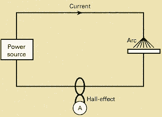
Fig. 1. Current measuring technique, ‘A’ showing the connection for the sensor
Current is normally measured by a Hall effect probe clipped around the cable. The current rating and accuracy of the probe needs to be taken into account.
Voltage measurement is a bit more difficult to get right as the voltage will vary depending where the connections are made. For true arc voltage, it is important to measure as close to the arc as possible, Figure 2. For MIG/MAG, a connection on the drive rolls, back at the wire feeder, will suffice. However, the voltage measured across the arc will be lower than that measured across the power source terminals, possibly by several volts, depending on the length and diameter of the welding cables and the amplitude of the welding current.
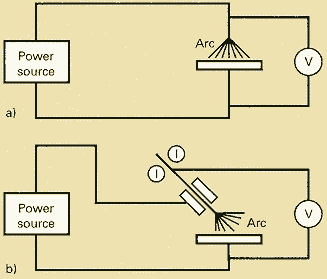
Fig. 2. Voltage measuring technique a) Connection to the back of the TIG torch; b) Connection to the back of the MIG gun
Care should be taken when measuring arc voltage in TIG welding as the high voltage used for starting the arc may damage the instrumentation unless it is specifically designed for arc monitoring.
Some standards now require heat input to be calculated from instantaneous values and this requires an instrument that can accurately record the waveform of the voltage and current and perform the calculation up to 5,000 times per second or more. An example of such an instrument is shown in Figure 3. Several other manufacturers provide similar instruments.
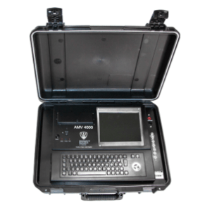
Fig. 3. AMV 4000 Data Logger – Triton Electronics Ltd
Such instruments can record and display the current and voltage waveform from pulsed TIG and MIG/MAG processes including controlled dip transfer and multi-pulse techniques.
Wire feed speed can be measured by clipping a tachometer to the wire or by attaching a sensor to the wire feed drive rolls. Temperature is measured using a thermocouple or resistance temperature detector (RTD) probe in contact with the surface or, alternatively, an infrared non-contact device. Although gas flow can be measured with a bobbin type gauge, for recording the value a mass flow type instrument is required.
Limits can be set (typically +/-10%) to indicate if the parameters have deviated outside of the procedure and statistical process control (SPC) can be used to stop or correct a process before problems occur. However, this is a relatively crude technique and TWI is investigating more advanced digital processing.
Copyright © TWI Ltd 2014
The content of this article was correct at the time of publication.
by Graham Fry
CIGWELD Transmig 185 Ultra
January 14, 2019 in Articles, Equipment
Take the guesswork out of welding with AUTO SET!
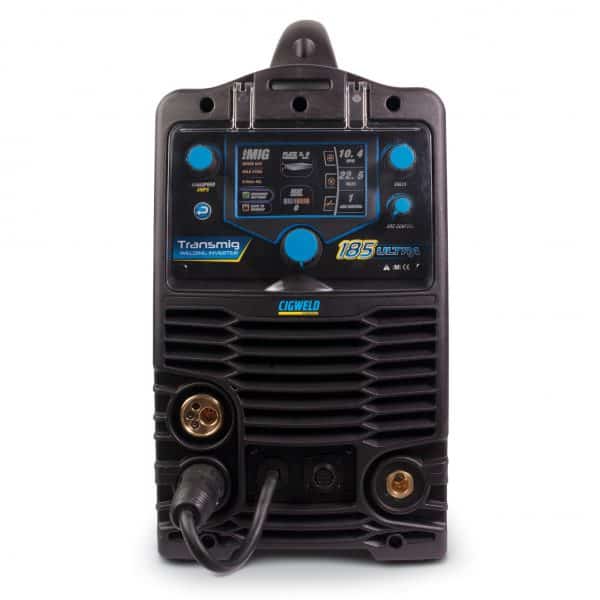
The Cigweld Transmig 185 Ultra features an impressive AUTO SET function that allows the user to weld like a Pro with no previous welding experience necessary.
Simply select the material type, thickness & consumable diameter and AUTO SET will pre-set the Wirefeed Speed (Amperage) and Voltage (MIG) along a pre-programmed synergic line. Experienced welders can then customise their settings by tweaking their wire speed and volts according to their technique and other factors. The AUTO SET function is available in all 3 processes: MIG, STICK and TIG!
Easily return to your previous weld thanks to a sophisticated Memory Function, or save up to 9 of your favourite weld settings!
The 185 Ultra comes with an integrated wire feeder that holds up to a 200mm spool, and boasts a range of Professional Features to ensure optimal welding results:
- Burnback Control
- Arc Control
- 2T/4T
- Spot/Stitch Weld
- Pre/Post Flow
- Up/Down Slope
- Arc Force
- Hot Start
- Anti-Stick
- VRD (applicable in Stick mode only).
Most importantly the 185 Ultra is fitted with a 10Amp plug, allowing you the flexibility to plug and play anywhere in your home or workshop.
The power source weighs just over 17kg, and all accessories can be packed inside a convenient purpose built Heavy Duty Backpack (W4018001), making the Ultra portable and ideal for any home or job site.
The 185 Ultra is back by a 3-year warranty and is fully compliant to Australian Standard AS 60974.1 and IEC 60974.1 so you know you have a safe product you can trust!
With excellent welding performance across a broad range of applications, anyone can weld like a pro.
You set the process and the Ultra will do the rest!
by Graham Fry
Welding Trade Tips: Fillet Weld Design
January 14, 2019 in Articles, Job Knowledge
Best practice in design is not simply a matter of deciding on the appropriate weld size or component thickness capable of carrying the service loads; there are many aspects of designing a welded component that need to be considered in addition to calculating permissible stresses. Weldability and mechanical properties such as tensile strength, toughness and fatigue resistance, all of which the designer must be familiar with, have been dealt with in a number of other Job Knowledge articles and will not be covered in this series on design.
In addition to selecting the material and specifying weld sizes, the designer must bear in mind that the decisions that he/she makes will directly affect the cost, safety and serviceability of the structure or component.
It is, therefore, necessary for the designer to:
- select the most appropriate material
- select the most cost-effective design of welded joint
- design the component to be welded by the most cost-effective process
- specify the smallest weld acceptable for both service and fabrication
- use the smallest number of welds
- ensure that there is adequate access for both welding and inspection
- ensure that realistic dimensional tolerances are specified and can be achieved
The topics mentioned above involve a range of specialised technologies and it is, therefore, essential for the designer to seek advice from other professions such as metallurgists and welding engineers and not to rely solely upon their own judgement. This must be done before the design process has proceeded beyond the point of no return; sadly this is often not the case!
To begin let us look at some definitions. Firstly, the joint type or configuration of which there are five fundamental forms as shown in Fig.1. Note that there are no welds associated with these joint types.
Fig.1. Joint types
|
In-Line or Butt Joint |
 T-Joint |
 Corner Joint |
 Lap Joint |
Edge Joint |
These various joint types may be joined by only two weld types. Firstly, the butt weld where the weld is within the plane of the components being joined and secondly, the fillet weld where the weld is completely or mostly outside the plane of the components (Fig. 2). Plug and edge welds are somewhat special cases and will be discussed later.
Fig. 2 Weld types
|
Butt Weld |
 Fillet Weld |
A butt weld may be combined with a fillet weld to form a compound weld as illustrated in Fig.3:
Fig.3. Compound welds
 Single-Sided T-Butt Weld |
 Single-sided T-butt Weld with superimposed fillet weld – a compound weld |
Fillet welds are probably the most common type of weld, particularly in structural steel work applications, so this first section will look at some of the design considerations of fillet welds. They may be used to make T, lap and corner joints (Fig.4).
Fig. 4. Single-sided fillet welded joint types
 |
 |
 |
A fillet weld is approximately triangular in shape, the size being defined by the weld throat or leg length as shown in Fig.5.
Fig. 5. Terms used to describe features of a fillet weld
 |
 |
 |
Fillet welds sizes should be specified preferably by referring to the throat thickness ‘a’ although the leg length ‘z’ is often used and can be easier to measure during weld inspection. Conventionally, the leg lengths are regarded as being of equal dimensions, the weld forming an isosceles triangle in cross section.
The convex fillet is generally undesirable for two main reasons. a)The junction of the weld metal with the parent metal at the weld toe can form a significant stress raiser and will adversely affect both fatigue life and brittle fracture resistance; b) the excess weld metal in the cap costs both time and money to deposit without contributing to joint strength. The concave fillet weld can be beneficial with respect to fatigue strength and, if required, the minimum throat thickness MUST be specified.
Fillet welds are less expensive to make than butt welds as there is no requirement to cut or machine a weld preparation. Although they are capable of carrying substantial loads they should not be used where the applied loads put the root of the weld in tension, particularly where the loading is dynamic – fatigue life, in particular, is drastically reduced. Where such loading is a possibility then a double-sided T-joint should be made using two fillet welds ( Fig.6).
Fig.6. Preferred fillet welded joint type under bending loads
It is commonly thought that the fillet weld is an easier weld for the welder to make than a butt weld as the weld is deposited on solid metal. However, this is not necessarily the case when full fusion into the root of the weld is required. It is not unknown for highly skilled welders to fail a fillet weld qualification test where this is a design requirement. This is an important point and needs to be considered first by the designer asking if it is an essential requirement and secondly by the fabricator when pricing a contract.
This also raises the point that the fillet weld is extremely difficult to volumetrically examine using non-destructive testing techniques to confirm its internal soundness. This applies particularly to the root region where it is not possible to measure, with any degree of precision, any lack of fusion, slag entrapment etc. Therefore the same reliance on joint integrity, and hence service performance, should not be placed on a fillet weld as may be placed on a fully inspected butt weld.
Fillet welds are the least costly weld type to make since the components to be joined do not require flame cutting or machining of a weld preparation, the pieces can be propped against each other and the welder can then deposit a single pass of weld metal against a solid metal backing.
Whilst this sounds simple there are some aspects of making a fillet weld that must be taken into account (in addition to those already mentioned.
Cooling rates in a fillet weld are greater than in a similar thickness butt joint. There are three paths by which heat will be lost from the weld. This fact means that lack of fusion/cold start defects is more likely, particularly in high thermal conductivity metals such as aluminium and the risks of cold cracking are increased in carbon and low alloy steels. What may be acceptable in terms of heat input and/or preheat temperature for a butt weld may therefore not be acceptable with a fillet weld configuration. This point has sometimes been overlooked, particularly when welding on temporary attachments such as strongbacks, where quality control may be somewhat lax. This has led to major cracking problems for some fabricators.
Unlike a butt weld where the required weld throat is generally the thickness of the parent metal, the size of a fillet weld is determined by the loads that it is expected to carry. It can therefore be of any size that the designer specifies although there are practical limitations with respect to both minimum and maximum throat thickness.
With the conventional arc welding processes, it is difficult to deposit a fillet weld with a throat less than some 2mm. This is in addition to the possibility of the lack of fusion/cold cracking mentioned above due to the rapid cooling rates experienced by small fillet welds. The maximum size of the fillet weld is generally that of the thickness of the thinner of the two items being joined but very large fillet welds may cause unacceptable distortion and/or extremely high residual stresses. In addition, above a certain size it may be more economical to make a T-butt, rather than a fillet weld.
Although the throat thickness is regarded as being the most important dimension for design purposes it is a fact that mechanical failure of fillet welds is often along the fusion line or through the parent material itself. One reason for this in carbon or low alloy steels is that the weld metal is mostly substantially stronger than the parent metal.
As mentioned previously there are a variety of fillet weld shapes that make the accurate measurement of the throat thickness a little more difficult than may be first thought.
The throat is the shortest distance from the root to the face of the weld. To measure this dimension in a regular mitre or flat faced fillet weld is relatively simple. The shape is that of an isosceles triangle, the throat being 0.7 of the leg length. Convex, concave and deep penetration welds, however have throat thicknesses as illustrated in Fig.7.
Fig. 7 Throat dimensions in fillet welds
 Concave fillet weld |
 Convex fillet weld |
 Deep penetration weld |
 Mitre fillet weld |
It is apparent then, that measurement of either leg length or actual throat thickness alone is not reliable in determining the design throat thickness of a weld but that the weld shape must be taken into account. The excess weld metal of the convex weld gives no benefit with respect to design strength and, from a cost point of view, the fillet weld face should be as flat as possible.
The deep penetration weld is a very cost-effective way of increasing the joint strength as only a proportion of the weld metal is from deposited filler metal. However, it is not possible to measure the throat of a deep penetration weld. To guarantee that the minimum design throat has been achieved it is necessary to control welding parameters and fit-up within very tight tolerances. This type of weld is therefore generally made using an automated or mechanised welding process (submerged arc or spray transfer MIG/MAG) in order to achieve sufficient and consistent control of the welding parameters.
When deciding on the size of a fillet weld it should be remembered that a small increase in throat thickness will result in a large increase in deposited weld metal as the cross-sectional area of a fillet weld is a function of the square of the leg length (area = z2/2). Increasing the throat from, say, 5 to 6mm results in an increase in area and therefore weld metal of around 45%. This equates to almost 0.1kg extra weld metal per 1 metre length of weld. There are thus substantial cost and weight penalties to be paid if the joint is either over-specified by the designer or over-welded by the welder. There are no hard and fast rules about the point at which it is more economical to change from a fillet weld to either a double-sided fillet weld or a partial penetration butt weld. Areas quoted in Fig.8 are worth bearing in mind when deciding on fillet weld sizes.
Fig. 8 Relative cross-sectional areas
For a fillet weld loaded in shear (the load parallel to the weld) the calculation of stress on the weld is simple; it is the load divided by the area of the weld throat.
It is assumed for design purposes that fillet welds fail through the throat and it is therefore a simple matter to calculate the cross-sectional area capable of carrying this applied load when the strength of the weld metal is known.
Note that the shear strength of a metal is generally around 70% to 80% of the tensile strength. This figure is often factored to give an acceptable margin of safety. In the UK for plain carbon steels a shear strength of 115N/mm2 is frequently used, enabling the throat thickness to be calculated from the simple formula throat:- throat ‘a’ = P/(L x 115).
The throat dimensions of a double fillet weld T-joint loaded in tension can be determined using the same approach. Note, however, that this is a very simplistic calculation and does not take into account any other stresses (bending, torsion etc) that the weld may experience. It is however beyond the scope of these brief articles to cover in any depth the stress analysis of welds.
Copyright © TWI Ltd 2014
The content of this article was correct at the time of publication.
by Graham Fry
Optimisation of Repair Schemes for Service Aged Components
January 14, 2019 in Articles, Job Knowledge
Low alloy steels are used extensively for high-temperature applications in power plants and the petrochemical industries but, while they have good weldability, they also present distinct challenges when they have been aged through service. This is because these steels, when service aged, are particularly susceptible to embrittlement and cracking.
Repair welding generally requires the use of a relatively high preheat, good interpass temperature control, and prolonged Post Weld Heat Treatment (PWHT). However, PWHT is difficult to perform in an in-service industrial environment, meaning that several welding procedures that do not require this process have been developed. These procedures are often referred to as ‘temper bead’ repairs.
While these non-PHWT procedures are permitted by many Codes and Standards the application of these techniques is not widespread. Furthermore, these non-PHWT procedures are not currently allowed by Codes and Standards for the repair of vanadium modified grades, which are claimed to be better suited for high temperature and hydrogen service.
Service Life Issues
A major problem associated with repair welding of service removed components is the possibility of temper embrittlement. Temper embrittlement refers to the decrease in notch toughness of alloy steels when heated in, or cooled slowly through, a temperature range of 400°C to 600°C. Temper embrittlement can also occur as a result of isothermal exposure in this temperature range and is caused by the presence of impurities such as antimony, phosphorous, tin, and arsenic.
Furthermore, low alloy steel welds are potentially susceptible to hydrogen-induced stress corrosion cracking (HSCC) and hydrogen embrittlement following repair and in a range of environmental conditions. As would be expected from a hydrogen embrittlement phenomenon, material susceptibility increases with increasing hardness, and hence control of the problem in practice is based largely on the avoidance of unacceptably hard microstructures. Even though the developed temper bead repair procedure may limit the hardness within generally acceptable limits to avoid SCC, there is a possibility of localised hard regions. Significant residual stress also may be present in the repaired location, which could make the repair location susceptible to SCC.
It remains to be determined how temper bead repair welds perform when compared with more conventional repair methods.
Despite the possibility that non-PHWT methods of repair can offer acceptable microstructure and adequate mechanical properties where they are permitted, there are still concerns over service life when applied in an industrial environment. Repaired locations can show significant residual stresses, which can have a detrimental effect on service life, including fatigue and corrosion fatigue performance in the repaired region.
Data
Currently, there is limited quantified data on the performance of both types of repair in typical service environments, which means that selecting the most appropriate repair route can be challenging.

Future opportunities
Additional data on the comparison between different repair methods on service aged Cr-Mo low alloy steel in a variety of service environments could be used to identify the most appropriate repair method, but would also improve the confidence in the integrity of a repair weld, and could save both time and money.
Further research could also assess the feasibility of using a temper bead repair for vanadium modified Cr-Mo steel, check how susceptible temper bead repair and conventional repair are to embrittlement, and assess each type of repair for their effect on service life. This testing would be particularly useful in regard to low alloy steels used in power plants and petrochemical industries.
TWI is looking to assess the factors involved and to build data on the different approaches in order to optimize repair schemes for service-aged components. A proposed project outline can be accessed
Copyright © TWI Ltd
The content of this article was correct at the time of publication.
by Graham Fry
Stainshield and Alushield: TIG welding
October 17, 2018 in Articles, Publications, Resources
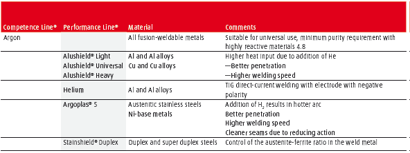
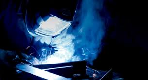
In TIG welding, the arc burns between the workpiece and a non-consumable tungsten electrode. To protect the electrode and molten pool from oxidation, both are shielded with an inert gas, generally argon. This welding process is suitable for all fusion-weldable metals. The type of current, polarity and shielding gas used depends on the base metal. TIG welding can be carried out both with and without filler metal.
Tips for when utilising additions of Helium or Hydrogen
The addition of hydrogen or helium is especially beneficial to heat distribution and heat transfer in the arc, particularly with TIG welding. The Performance Line® offers a broad range of specialty gases that, owing to their hydrogen or helium content, enable a distinct increase in productivity.
Agroplas®5 is primarily recommended for TIG welding of austenitic stainless steels and some nickel-based alloys. The hydrogen content in the gas permits more energy to be transferred to the metal. This, in turn, results in deeper penetration and/or greater welding speeds. The hydrogen content may be as much as 15%, although the realistic upper limit for manual welding is 5%. As a rule, gases with a higher hydrogen content are only recommended for mechanised welding, since it is more difficult to control the heat and the pool is very fluid. Gases containing hydrogen must not be used to weld aluminium or titanium alloys or steels sensitive to hydrogen since this can lead to greatly increased porosity or embrittlement.
Since helium (like argon) is an inert gas, the gas mixtures in the Alushield® series can also be used for aluminium alloys, all types of steel, and for gas-sensitive metals.
Stainshield® Duplex was developed especially for TIG welding duplex steels or fully austenitic materials. The addition of nitrogen causes the austenisation of the weld metal, which is particularly beneficial when TIG welding duplex steel without filler metal. These gases have also proven valuable for low-ferrite welding of high-alloy metals in the chemical industry.
TIG Shielding gases at a glance
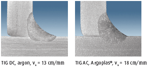
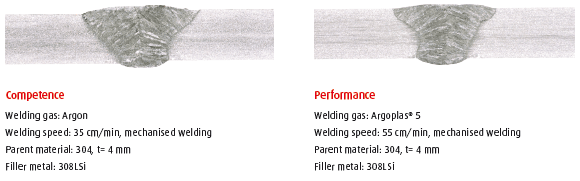
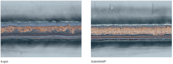
Argoplas®5 improves speed of welding and penetration
Manual welding of stainless steel 304, sheet thickness 4 mm
TIG Welding of Stainless Steel Argon versus Argoplas®5
BOC – A Member of the Linde Group, Mr Kyle Scott Market Manager – Welding and Industrial Gases, South Pacific
E-mail kyle.scott@boc.com
by Graham Fry
Shielding gases for arc brazing
October 17, 2018 in Articles, Publications, Resources
Gas metal arc brazing (GMA brazing) is an alternative method for joining primarily thin (t < 3.0mm) sheets that have been coated for corrosion protection. This method offers considerable advantages over GMA welding since an alloy metal with a lower melting point than the base metal is used as filler metal.
- Lower heat input
- Less burn-off of the coating
- Corrosion-resistant, copper-based filler metal
- Much less spatter formation
- Almost no seam corrosion
- Reduced distortion
- Good gap bridging
The right choice of shielding gas can further boost these positive properties. In addition to the shielding gas, other key factors influencing the quality of the join are the base metal, the type and thickness of the coating, and the alloy used for the filler metal.
The shielding gas has a varying effect on the final brazing result, depending on the type of bronze used and the base metal or its surface condition. Argon is the universal shielding gas for GMA brazing since it can be used with all wire, for all types of arcs and in all positions. It offers impressive all-round properties and a low heat input. The disadvantages of argon are somewhat unstable arc and a tendency towards porosity. Although the very small gas pockets do not have a negative effect on the strength of the joint, they appear if the seam is being polished. This results in extensive finishing work, particularly in visible areas.
When brazing coated sheets with silicon bronze, the result can be improved by adding active components. Stainshield® (1%Oxygen Balance Argon) in particular stabilises the arc and reduces porosity. The slightly increased heat input in comparison with argon translates into higher process speeds and improved wetting.
When brazing with aluminium bronze alloys, the amount of active component content in the shielding gas has to be restricted. However, here too, adding specific quantities of inert helium can also improve the final results. Products in the Alushield® series improve seam appearance, offer outstanding flow and wetting properties and, owing to a much higher brazing speed, also result in a lower heat input.
Performance Line® shielding gases are also the gases of choice for brazing stainless steel. Since no zinc vapours are produced that disturb the arc, the above mentioned advantages are even more pronounced.
Tungsten inert gas (TIG) or plasma arc (PA) brazing are also possible. Since the tungsten electrode cannot be used with gases with high active-component content, only inert argon or gases in the Alushield® series can be used.
Low melting point of the copper alloy enables lower heat input and thus lower Zn vaporisation with coated sheets
Improvement in process stability, seam appearance, and wetting
With robotic GMA brazing of coated sheets with silicon bronze using Stainshield®
BOC – A Member of the Linde Group, Mr Kyle Scott Market Manager – Welding and Industrial Gases, South Pacific
E-mail kyle.scott@boc.com
by Graham Fry
Alushield: MIG welding of aluminium alloys
October 17, 2018 in Articles, Publications, Resources
MIG welding of aluminium can be performed in the short, spray or pulsed arc. The advantages of the pulsed technique are that spatter formation is reduced and a wire electrode with the next largest diameter can be used. The larger diameter wire is easier to feed and, at an identical melt-down rate, has a smaller surface area. Consequently, fewer impurities and less moisture are introduced into the weld seam via the wire.
Argon is by far the most frequently used shielding gas for MIG welding of aluminium. It has impressive all-round properties and can be used for all types of arcs and in all positions. Further improvement can be achieved by using Alushield®mixtures.
Performance Line® gases are used in cases in which higher quality seams and increased welding performance are required. All gases in the Alushield® series contain helium, which makes the arc hotter, broader and more stable.
Benefits of using Alushield®
- Reduced porosity
- Improved penetration, prevents lack of fusion
- Higher welding speeds
- Better gap bridging
- Less/no preheating of thick-walled components
- The more uniform heat input and better directional stability, facilitates the welding of components of different thermal conductivity, for example, in differing material thickness.
- Reduced notch effect and better distribution of forces thanks to wider, flatter weld beads.
Tips for MIG welding when shielding gases contain helium (Alushields)
Arc voltage
A higher helium content requires a higher arc voltage at an identical arc length.
Bead shape
A greater helium content results in a broader and flatter seam at the same welding speed. The ‘argon finger’ is less pronounced and fusion penetration is rounder and deeper. This is advantageous, particularly in the case of dynamic loads.
Shielding gas flow rate
Helium is lighter than air. This has to be taken into account both when measuring throughout and when adjusting the minimum shielding gas flow rate..
GMA Welding of Aluminium Argon versus Alushield® Shielding Gases
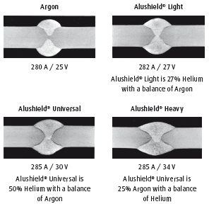
Parent metal EN AW-5754 [AlMg3] t = 10 mm
Filler metal ISO 18273 – S Al 5183 (Al Mg4.5Mn) ø = 1.6 mm
BOC – A Member of the Linde Group, Mr Kyle Scott Market Manager – Welding and Industrial Gases, South Pacific
E-mail kyle.scott@boc.com
by Graham Fry
Stainshield: GMA welding of stainless steels
October 17, 2018 in Articles, Publications, Resources
The shielding gases used for stainless steels differ from those used in GMA welding of unalloyed steels since they contain much less active gases, such as oxygen and carbon dioxide. This is necessary to prevent excessive oxidation of the passive layer responsible for the corrosion resistant properties of these metals. It is important to remember that the oxidation properties of oxygen are much greater than those of CO2. However, welding in an inert atmosphere, for example, with argon, is not recommended either since the arc is unstable penetration is significantly decreased and bead shape is poor.
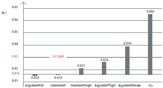
The carbon content of the weld metal is a key factor in ensuring resistance to intergranular corrosion. In stainless steels with particularly low carbon contents, referred to as ELC steels, the carbon content of the weld metal should not exceed 0.03%. To prevent unacceptably high carbon pickup from the shielding gas, the CO2 content of the above-mentioned products should be limited to a maximum of 2.5%. If welding is performed correctly, this prevents sensitisation to intergranular corrosion. The graph on the right illustrates the tendency of various shielding gases to cause the carburisation or decarburisation of the weld metal.
These guidelines apply if a solid wire or a metal-cored wire is used as filler metal. However, if a slag-forming flux-cored wire is used, the shielding gas recommended by the manufacturer should be used. An Argon/Carbon Dioxide shielding gas is usually recommended for these wires, e.g. Argoshield® 52, since the slag that forms prevents oxidation or carbon pickup.
Carbon pick-up and loss with different shielding gases
Carbon content of the wire electrode: 0.016 %
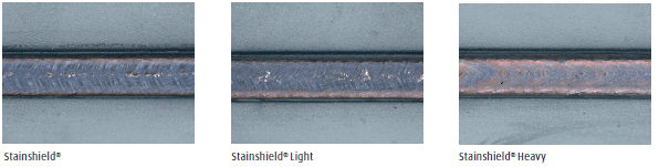
Impact of gases on surface oxidation
GMA fillet welds on stainless steel 304, sheet thickness 8mm, mechanised welding
The following table shows the weld cost calculation comparing Stainshield to Stainshield Heavy.
These evaluations are imperative to make the correct selection of the optimum shielding gas for your application.
Welding Gas Trial. Time/Cost Study
| General Data | ||||||||||
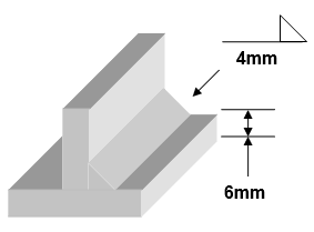
| 1 | Type of seam | Fillet | 7A | Labour costs | $65.00 /hr | |||||
| 2 | Welding position | PB | 7B | Labour costs | $1.08 / min | |||||
| 3 | Plate thickness | 6 mm | 8 | Wire costs | $18.00 k/g | |||||
| 4 | Throat/Leg Length | 4 mm | 9 | Gas 1 Stainshield | $8.00/ m3 | |||||
| Material Length 1 M | 10 | Gas 2 Stainshield Heavy | $22.00/ m3 | |||||||
| 5 | Wire diameter mm | 0.8 | 1.0 | 1.2 | 1.6 | |||||
| 6 | Wire spec. | Steel | 3.95 | 6.2 | 8.9 | 15.8 | ||||
| Weight g/m | Alu. | 1.36 | 2.12 | 3.05 | 5.43 | |||||
| Pre-set and measured parameters | Gas 1 | Gas 2 | ||||||||
| 11 | Voltage / Current | 148 A/14.3 V | 150 A/ 15.8 V | |||||||
| 12 | Wire feed speed | 5 m/min | 5 m/min | |||||||
| 13 | Gas flow rate | 15 l/min | 18 l/min | |||||||
| 14 | Type of wire electrode | Solid | Solid | |||||||
| 15 | Wire diameter | 1.2mm | 1.2mm | |||||||
| 16 | Arc on time th | 4.16 min | 3.48 min | |||||||
| 17 | Process related costs t h process (Cleaning time) | na | na | |||||||
| Consumables | ||||||||||
| 18 | Wire electrode (12x16x6) | 185.12 | 154.86 | |||||||
| 19 | Shielding gas (13×16) | 62.4 ltrs | 62.64 ltrs | |||||||
| Costs | ||||||||||
| 20 | Labour costs (th) (7Bx16) | $ 4.49 | $ 3.76 | |||||||
| 21 | Labour costs (th) 7Bx17) | na | na | |||||||
| 22 | Wire electrode costs (18×8/1000) | $ 3.33 | $ 2.79 | |||||||
| 23 | Gas costs (9 or 10×19/1000) | $ 0.50
|
$ 1.37 | |||||||
| Total to weld 1000mm component | $ 8.32 c | $ 7.92 c | ||||||||
by Graham Fry
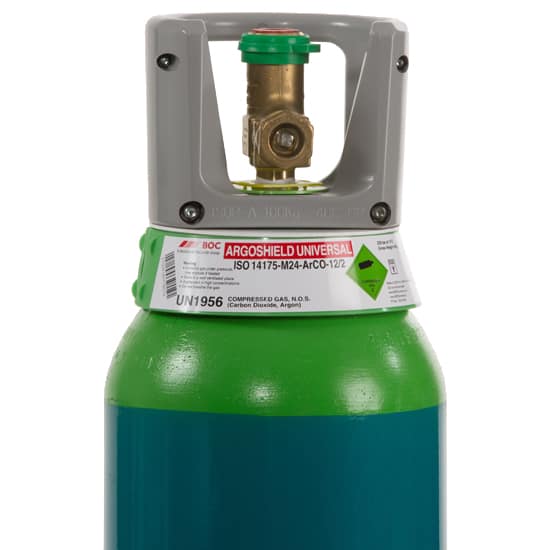
Argoshield: GMA welding of structural steel
October 17, 2018 in Articles, Publications, Resources
The collective term ‘structural steel’ refers to unalloyed and low-alloyed steels, fine-grained structural steels that are suitable for welding mild steel. The choice of the most suitable shielding gas depends mainly on the type of filler metal, the material thickness and surface condition of the base metals, the degree of mechanisation, working position, arc type and the requirements of the welded joint.
GMA welding with solid-wire electrodes and gas mixtures, consisting of Argon, CO2 and O2, such as Argoshield® Universal, is by far the most common method for joining structural steels. Owing to their unbeatable advantages in terms of quality and economy, gas mixtures are now much more widely used than pure CO2. Thus, the general rule of thumb applies to how much active gas, CO2 or O2, should be used: as little as possible and as much as necessary. Due to the increasing degree of mechanisation and the greater use of pulse techniques, mixed gases with a reduced CO2 or O2 content are becoming increasingly popular.
However, a lower level of active gases results in lower heat input, which can jeopardise fusion penetration and welding performance. In this respect, helium ad mixtures have proven effective in many applications.
A Helium content of 20–40% can improve heat transfer from the arc to the component, however, without the known disadvantages of the oxidising components. The increased efficiency of Argoshield® 100 gas can be used either for achieving higher welding speeds or for improving quality, such as better gap bridging or for reducing the risk of lack of fusion.
The shielding gas for metal-cored wires is selected according to the same criteria as those for solid-wire electrodes. These cored wires are flexible with regard to special alloying components and are characterised by a generally soft arc. Thanks to the powder filling, the power required for melting is lower than at comparable melt-down rates with solid-wire electrodes; this can also lead to a lower heat input.
Slag-forming flux-cored wires offer advantages for certain tasks. For example, when welding out of position, a quickly solidifying slag can act as a backing. By carefully defining the filling composition, the chemical and metallurgical reactions in the weld pool can be affected. As a rule, Argoshield® 52 or CO2 is used; lower levels of CO2 are not recommended since penetration can become critical.
Influence of gas components on penetration and bead surface: as an example, a fillet weld on a T-joint, steel thickness 10 mm
Fully mechanised GMA–robot weldments with constant travel and wire feed speed
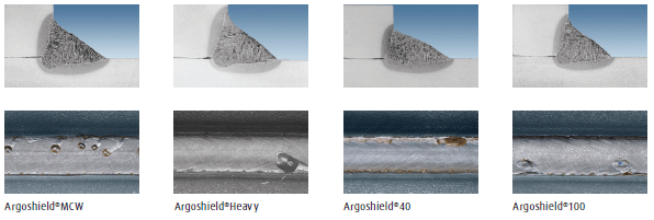
Effect of shielding gas composition on the GMAW process and result
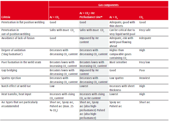
Stainless Steel GMAW Shielding gases at a glance
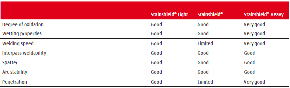
BOC – A Member of the Linde Group, Mr Kyle Scott Market Manager – Welding and Industrial Gases, South Pacific
E-mail kyle.scott@boc.com
by Graham Fry
World-class aluminium welding with Kemppi. Buster Boats: Case Study
October 17, 2018 in Articles, Equipment, Welding
Buster Boats
The future of Power Boating
World-class aluminium welding precision with Kemppi X8 MIG Welder
Buster Boats are manufactured at the Inha Works located in Ähtäri, Southern Ostrobothnia region of Finland. The boat range varies from four meters to over nine meters, from 2 horsepower up to even 700 horsepower. The key to success at Buster Boats is based on good quality as well as strong product development and R&D. The Inha Works employs about 150 persons, of which 30 are welders.
Durability, safety and ease of use were taken as the starting points when designing the new boat range already in 1976. Through the years, almost 125,000 Buster Boats have been manufactured for satisfied boaters around the world. Buster is trusted by both recreational and professional users. Buster Boats was recently sold to Yamaha Motor Europe and the company has a bright future ahead.
WORLD-CLASS ALUMINUM WELDING: Buster Boats is a well-known aluminium boat manufacturer and a market leader in its industry. They excel in producing highly reliable, low-maintenance boats, and in R&D. Kemppi solutions, such as the new X8 MIG Welder, as well as joint R&D are signposts on the road to success for Buster Boats.
Main challenge
“Welding aluminum is quite demanding, and this calls for first-class welding machines. Also, all welders must be trained for the job and their qualifications are regularly controlled. We have daily quality controls and an inspection record is made of each boat,” says foreman of boat manufacturing Kimmo Multaniemi. Even though manual welding cannot be made much faster, Buster Boats highly appreciates usability that also helps to save time: even one minute per boat can lead to 2,000 minutes less production time in one year. Buster Boats has analysed all products and tasks to the point that the workers know to the minute how much time they can spend on each operation.
“X8 MIG Welder is a first-class equipment for demanding, high-quality aluminium welding in terms of both from the arc performance and usability point of view.“
– Kimmo Multaniemi, Foreman, Boat Production, Buster Boats
Kemppi’s solution
Buster Boats was among the first Kemppi partners to test the new X8 MIG Welder – and to bring it into play. The joint R&D with partners is pivotal for Buster Boats. “That benefits both of us,” Multaniemi says. “Our cooperation with Kemppi goes a long way back and this is why we have decided to continue on this path. Kemppi has been a good supplier for us because we have also been able to participate in the R&D of new products. We want to do R&D with Kemppi to have even better machines,” Multaniemi adds. Multaniemi also values the meaning of new innovations for the welders. “I’ve always lived by the philosophy that the easier it is for my welders to work here, the easier it makes my work for me.”
X8 MIG Welder stands for welding comfort with great arc performance, and it’s extremely suitable for challenging aluminium welding. X8 MIG Welder redefines ergonomics in the welder’s most important tool, welding guns: the hand grip, mobility and stability have been optimised to meet the requirements of the most demanding welding tasks. “The welding gun is really good. It feels better than the previous one,” welder for Buster Boats Kari Urrila comments on his first experiences with the X8 MIG Welder. Urrila has also been impressed by the X8 Wire Feeder. “The wire feeder is really good. It’s placed lower than in the previous models and it’s neater to insert the wire into the feeder.”
by Graham Fry
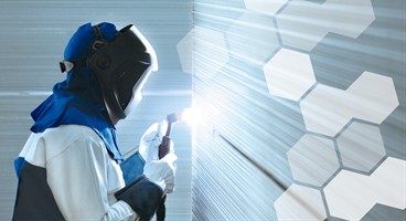
Shielding Gases: Commodity or Welding Optimisation Tool?
October 17, 2018 in Articles, Publications, Resources
Abstract
In fabrication or construction, the goal is higher product quality with improved performance. This is especially important with relation to the GMA and TIG welding processes. I have heard many people comment to me that shielding gases only protect the welding arc from atmospheric attack whilst this is partly true, shielding gases do much more than that. This paper will explore and explain the properties of various shielding gases and clearly show the benefits of selecting the correct shielding gas for the right application. I have broken this down into material types and also processes using various shielding gases. The under utilisation in the South Pacific of shielding gases containing additions of hydrogen, helium and nitrogen are compared with traditional mixtures such as argon and the benefits are staggering. The quality and economics are quantified and it is clear that using the correct shielding gas shows dramatic benefits. The economics have been qualified by completing a weld-cost calculation. This was achieved using a Linde DMG5 data logger. I believe we should no longer call these products shielding gases moving forward but welding gases as they do much more than shield the molten metal or arcs from atmospheric attack. Shielding gases are an optimisation tool and not a commodity.
Introduction
Shielding/Welding Gases with a balance gas of Argon and additions of Carbon Dioxide and Oxygen or mixtures thereof have been utilised since the early 1970’s commercially. My late friend, mentor and colleague Mr Hans Pomaska was very active in the development of these types of mixtures. Continuing on from his work we now use additions of hydrogen, helium and Nitrogen or mixtures thereof. The benefits and percentage of mixtures are explored and explained in many laboratory trials ,papers and field work with a clear focus on the selection of the correct Argoshield® Stainshield® or Alushield®. With Linde and BOC coming together the depth of knowledge and understanding in this field is second to none.
The role of shielding gas – What shielding gas can do
The primary function of the shielding gas in gas-shielding arc welding has been to protect molten and heated metal from the damaging effects of the surrounding air and to provide suitable conditions for the arc. If air comes in contact with the molten or heated metal, the oxygen in the air will oxidise the metal, the nitrogen might cause porosity or brittleness in the weld metal, and moisture from the air may also cause porosity.
The shielding gas composition affects the material transfer from the molten electrode to the weld pool, which in turn influences the amount and size of the spatter created. It also affects the appearance of the weld bead, the weld geometry, the welding speed and plays a key role in the burn-off of alloying elements (which affects material strength) or oxide formation on the bead surface. These effects can be clearly demonstrated in real time using BOC’s new GMA and TIG arc projectors.
The influence of shielding gas upon GMA welding
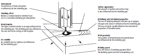
Environment
- The emission of fumes and gases is influenced by the shielding gas.
Shielding effect
- Molten metal or tungsten electrode is shielded from the air in a controlled shielding gas atmosphere.
Metal transfer
- The type of metal transfer is strongly influenced by the shielding gas. The shielding gas also influences the size and forces acting on the droplets.
Arc stability
- Arc stability and arc ignition are influenced by the shielding gas.
Surface appearance
- The amount of spatter and surface slag is also influenced by the shielding gas.
Metallurgy and mechanical properties
- The loss of alloying elements and pick-up of oxygen, nitrogen, and carbon is influenced by the shielding gas. This loss and pickup will influence the mechanical properties of the weld metal.
Weld geometry
- The profiles of the weld bead and penetration are influenced by the shielding gas.
Welding speed
- The choice of shielding gas will affect the welding speed and the total welding cost.
Effects of the different shielding gas components
Argon
Argon (Ar) is an inert gas. This means it does not oxidise and that it has no effect on the chemical composition of the weld metal. Argon is the main component in most shielding gases for GMA and GTA welding.
Carbon dioxide and oxygen
Pure argon cannot be used for GMA welding of steels since the arc becomes too unstable. An oxidising gas component is therefore used to stabilise the arc and to ensure a smooth metal transfer during welding. This oxidising component may be Carbon Dioxide (C02), Oxygen (02) or a combination of these gases. The amount of the oxidising component added will depend on the material type and application.
The electrical arc in gas metal arc welding can be divided into three parts: the arc plasma, the cathode area and the anode area. In GMA welding, where the filler metal constitutes the positive electrode (the anode), the cathode area is on the workpiece in the form of one or more cathode spots. The oxidising additive is necessary to stabilise these cathode spots, otherwise the arc tends to flicker around on the surface of the workpiece, forming spatter, irregular weld beads and minimal penetration.
![]()
The metal transfer and penetration profile can be changed by selecting different argon-carbon dioxide mixtures. The figure above shows the type of metal transfer in spray arc and typical penetration profile for mixtures with 2% C02 up to pure C02. Higher C02 content gives better side wall penetration but more spatter and fume. For most applications, the penetration given by a few percent of C02 is acceptable. A spray arc cannot be achieved when using 100% C02.
Carbon dioxide or oxygen?
There are often advantages in using C02 in argon. One is the slight improvement in weld geometry and appearance over oxygen-argon mixtures. This occurs because of the differences in weld pool fluidity, surface tension and oxides in the molten metal. With C02 instead of 02, there is also less oxidation and slag formation which can have an effect on the appearance of the weld as well as the need for cleaning the weld.
Another advantage is improved penetration, especially side wall penetration. This is mainly a factor of the higher arc voltage and the energy employed when welding with C02 in the mixture.
Helium
Helium (He) is like argon – an inert gas. Helium is used together with argon and a small percent of C02 or 02 for GMA welding of stainless steel. In its pure state, or mixed with argon, it is used as a shielding gas for GTA and MIG welding. Compared with argon, helium provides better side wall penetration and higher welding speeds, by generating a more energy-rich arc. The process is more sensitive to arc length variations with helium as a shielding gas, however, the arc is more difficult to strike when TIG welding.
Hydrogen
Hydrogen (H2) can be added to shielding gases for GTA welding of austenitic stainless steels in order to reduce oxide formation. The addition also means more heat in the arc and a more constricted arc, which improves penetration. It also gives a smoother transition between the weld bead and base metal.
For root protection purposes, hydrogen addition is commonly used. It is not recommended for root purging of ferritic,martensetic,aluminium,titanium,,Duplex steels. For this application, argon or high purity nitrogen should be used.
Nitrogen
Nitrogen (N2) is used as an additive in shielding gases for GTA welding of austenitic, duplex and superduplex stainless steels. These steels are alloyed with up to 0.5% nitrogen in order to increase the mechanical properties and resistance against pitting. If the shielding gas contains a few percent of nitrogen, nitrogen losses in the weld metal can be reduced. Nitrogen with 5% hydrogen is a common purging gas that delivers a good reducing effect. Pure nitrogen will further increase pitting resistance at the root when welding austenitic duplex and superduplex stainless steels.
Properties for specific uses
An in-depth understanding of the ‘internal properties’ of gas components and their interaction in specialised mixtures is essential for successful use of process gases in specific welding applications. The welding arc itself, a highly efficient but complex tool, consists largely of different amounts of ionised gas and metal vapour. This means the physical properties of the gas have a direct and immediate impact on the arc. In addition, the process gases also contact the hot metal, a highly reactive area, in which the chemical and metallurgical effects of the gases also play an important role. The following criteria serve as examples only and do not claim to be complete.
Dissociation and ionisation energy
Ionisation occurs directly in the case of the monatomic inert gases, Ar and He. Diatomic or polyatomic gases, such as H2 or CO2, have to be initially dissociated in the arc, a process which requires additional energy. The less energy required for these processes, the easier it is to ignite the arc. If components that are comparatively difficult to ionise, such as He or CO2 are present, the welding voltage has to be increased accordingly. However, this additional electrical energy is released again in the form of recombination energy, which can both improve heat input and increase welding speed.
Thermal conductivity
Some of the arc’s heat is transferred to the workpiece via the plasma or gas flow. Especially at high temperatures, the two components He and H2 can significantly improve process efficiency. Good thermal conductivity has a positive effect on seam beadshape, wetting action, degassing of the molten pool – and on welding speed.
Chemical reactivity and metallurgical impact
CO2 and O2 are both active, oxidising gases. Especially at high temperatures, they react quickly with the materials present to form oxides. In appropriate quantities, metal oxides can improve edge wetting, arc stability. If larger percentages of active gases are present, for example, when GMA welding structural steel, the resulting increase in oxidation generates additional heat. The product of oxidation, otherwise known as ‘slag’ or ‘silicate’, is often found on the surface of the bead. O2 as a shielding gas component has a greater oxidising effect than the same quantity of CO2. If quality demands require lower levels of these deposits, the active gas component in the Argoshield®/Stainshield® series can be reduced. However, this should only be done if requirements regarding fusion, penetration and the number of pores are taken into consideration. In the case of a higher CO2 content, carbon pickup may occur, depending on the material being welded.
Thermal conductivity of the gases
Heat transfer from the arc to the base metal depends on the thermal conductivity of the different gases. Helium and hydrogen offer particularly high thermal conductivity values.

N2 is considered a low-activity gas, i.e. whether or not reactions take place depends on the metal and the process conditions. An example of positive reactivity is the austenitising effect of Stainshield® Duplex gases when TIG welding fully austenitic materials or duplex steels. In contrast, the pore-forming or embrittling effect of N2 with GMA welding steel is detrimental.
H2 is unique as a particularly effective reducing component for arc welding. It can be used, for example, in TIG/PAW welding and purging of austenitic stainless steels with Argoplas®5 gas, in other words, in cases in which it is important to prevent oxidation of very expensive and sensitive metals. Owing to their superior thermal conductivity and additional recombination energy, Argoplas®5 gas permits much higher TIG/PAW welding speeds than argon. Unfortunately, these extremely beneficial properties cannot be used for welding all metals. For example, H2 leads to pore formation in aluminium and to cracks in ferritic steels. Thus, H2’s compatibility with a given material always has to be tested.
Ar and He are the inert gases used in welding. Since they do not react with any metal, they can be used with all metals that can be fusion welded.
Other relevant properties:
- Relative density: influences the position-dependent effectiveness of the shielding gas
- Heat transfer coefficient: He can transfer heat to a metal surface much more effectively than Ar
Dissociation and ionisation energy of the gas components
Parameters for ignition properties, welding voltage and arc energy.
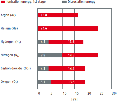
Purity levels and mixing accuracies
Shielding gases are standardised in AS 4882 and ISO 14175. These standards specify, amongst other things, the minimum quality requirements of the components and mixtures. However, depending on the material, process, method and quality requirements, higher qualities may be necessary depending on the application. An example is Argon 5.0 (99.999%) is required when welding titanium components.
Conclusion
When selecting a shielding gas for your application, you should consider more than just the cost of the gas. This is quantified in the two weldcost calculations comparing Argon vs Argoplas 5 in the TIG process welding stainless steel and Stainshield Light vs Stainshield Heavy with the GMA process on stainless steel. The shielding gas can be more than twice as expensive and still the overall welding costs can be reduced considerably. Other comparisons or trials that have been conducted are Argon vs Alushield Heavy with GMA Welding and Argon vs Alushield Universal with the TIG Welding process on Aluminium. These cost evaluations have shown similar benefits. It is clear that the quality and economics of welded structures can be greatly improved with the correct selection of a shielding/welding gas. This is very much dependant on the process, material type, wire diameter, power source etc. Some common applications have been explored with favourable results in regards to the additions of helium and hydrogen. Thanks to our considerable field experience, it is possible to increase productivity with a decrease in overall costs due to the correct selection of Argoshield®, Stainshield® or Alushield® (as will be reviewed in further detail in upcoming articles). Process efficiency can be considerably increased by the combination of know-how of gases and their interaction with the processes. If the welding process is the bottle neck in your production, then a through investigation into your welding process should be undertaken. The investigation may well show that the introduction of the optimum shielding gas or gases may be your answer. In conclusion shielding gases are in fact an optimisation tool and not a welding commodity.
BOC – A Member of the Linde Group, Mr Kyle Scott Market Manager – Welding and Industrial Gases, South Pacific
E-mail kyle.scott@boc.com
References
- Linde AG Industrial Gases division -The Linde working Group , Peak performance through innovation and expertise.
- Linde AG Ammann T,Unterschleissheim Gas shielded Arc Welding of Duplex Steels
- Linde AG Kersche A, Trube S, Hoellriegelskreuth, Shielding Gases for Gas –shielded Metal Arc Brazing
- AGA, Industrial Gases division, The AGA working Group, The Shielding Gases Handbook
Acknowledgements
- Mr Peter Kuebler from Linde/BOC for his support in editing this paper.
- Mr Ernst Miklos and the Linde Applications department in Lohof Germany with whom I have worked closely with over the last 22 years on the development of welding gases.
- Mr Bob Eden from Linde/BOC UK with whom I have exchanged practical experiences with over many years.
- The Applications Engineers and Welding specialist from Linde/BOC South Pacific who have conducted many practical trials on Welding Gases in the market.