So far in this welding expertise article, we’ve covered welding imperfections such as cracks, lack of fusion, incompletely filled grooves and root concavity, among other imperfections.
This third and final instalment is all about the imperfections that occur with fillet welds and how to avoid them.
This article will specifically focus on:
- Excessive convexity
- Oversized fillet welds
- Undersized fillet welds
- Asymmetric fillet welds
- Poor fit-up
Excessive convexity
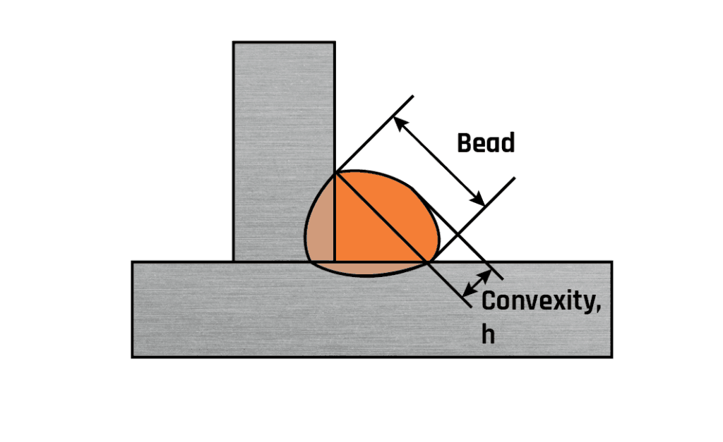
Fig 1. Excessive convexity
This feature is also covered by the definition for excess weld metal (see Part 1) and may be described as weld metal lying outside the plane joining the weld toes. Note that the term ‘reinforcement’, although used extensively in the ASME/AWS specifications is avoided in Europe as it implies that excess metal contributes to the strength of the welded joint. This is rarely the case.
Common causes
Poor technique and the deposition of large volumes of ‘cold’ weld metal.
Acceptance
The idealised design requirement of a ‘mitre’ fillet weld is often difficult to achieve, particularly with manual welding processes.
BS EN ISO 5817 acceptance is based on a mitre fillet weld shape with a specific design throat and any excess weld metal is measured in relation to this mitre surface. The limits for this imperfection relate the height of the excess metal to the width of the bead with maximum values ranging from 3mm for a stringent quality level to 5mm for a moderate quality level. Surprisingly, there is no reference to a ‘smooth transition’ being required at the weld toes for such weld shape.
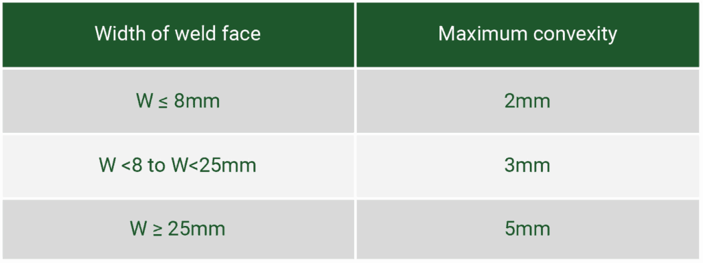
AWS D1.1 also has limits relating width to acceptable excess as follows:
Avoidance
Welder technique is the major cause of this problem and training may be required. It is also important to ensure that the parameters specified in the welding procedures specification are adhered to.
Oversize fillet welds (welds with a throat larger than required by the design)
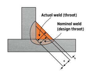
Fig 2. Oversize fillet weld
As discussed previously, oversized fillet welds can represent a significant additional cost and loss of productivity.
Common causes
There are some welding-related causes, eg high welding current, slow travel speeds, and some supervision related (eg ‘to be safe make this fillet bigger by x mm’).
Acceptance
BS EN ISO 5817 has limits related to the actual throat (eg for stringent quality levels, the actual weld throat [a] may exceed the nominal (design) weld throat [h] by 1+0.15a with a maximum of 3mm. For the moderate quality level (D) the excessive throat thickness is unlimited.
Avoidance
Adhere to the specified welding procedure and parameters and do not add to the specified weld size. Where possible mechanise the welding operation.
Undersized fillet welds (fillet welds smaller than those specified)
Undersized fillet weld
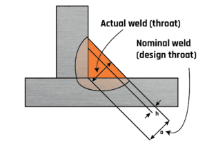
Fig.3. Undersized fillet weld
Common causes
The welding-related causes are associated with high welding speeds and low welding currents.
Acceptance
Therefore, it is normally assumed that fillet welds will be at least of the size specified. BS EN SIO 5817 states that limits to insufficient throat thickness are not applicable to processes with proof of greater depth of penetration, therefore a fillet weld with an apparent throat thickness smaller that that prescribed should not be regarded as being imperfect if the actual throat thickness with a compensating greater depth of penetration complies with the nominal value. That is if we can be sure there is good penetration the smaller fillet may be acceptable, however, this should be discussed with the designer of the fabrication. The limits set by the standard.
Relying upon deep penetration to provide the required minimum design throat thickness can be difficult to justify. Penetration is a weld characteristic that is hard to measure directly and reliance must be placed on the stringent control of both the welding process and the welder. Manual welding can rarely be relied upon to provide the required consistency but it is an option with mechanised welding systems.

Avoidance
Adhere to the specified welding procedure and parameters. Use sufficient current and appropriate travel speed. Where possible mechanise the welding operation.
Asymmetric fillet weld (a fillet weld where the legs are of unequal length)
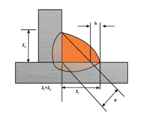
Fig 4. Asymmetric fillet weld (a fillet weld where the legs are of unequal length)
Common causes
Due to incorrect electrode positioning or to gravity pulling the molten pool towards one face of the joint. It is an mainly a problem with fillet welds made in the horizontal/vertical (PB) position.
Acceptance
There are instances where asymmetry may be specified (eg to place the toe stress concentration in a particular region).
BS EN ISO 5817 would, for a 10mm leg length fillet weld (ie 7.1mm throat) allow a difference in leg lengths of about 2.5mm at the stringent quality level and 3.4mm at the moderate quality level. Acceptance is related to throat thickness.
The consequence of this imperfection is a significant increase in weld volume. Provided the leg length requirement is achieved there would not be a loss of strength. Perhaps this is why, in other standards, a requirement is not specified and the acceptability is left to the inspection personnel to make the ‘engineering judgement’.
Poor fit-up
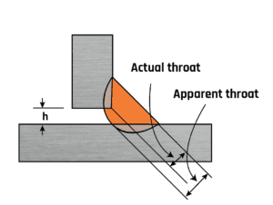
Fig 5. Poor fit-up
The most common imperfection is an excessive gap between the mating faces of the materials.
Common causes
Poor workshop practice, poor dimensioning and tolerance dimensions on drawings.
Acceptance
A major problem with fillet welds is ensuring the gap between the components is within defined limits. BS EN ISO 5817 specifies the acceptance criteria as follows:

Where h = fit-up gap and a = fillet weld design throat
Figure 5 shows that the gap results in a reduction in the leg length on the vertical plate and this, in turn, results in a reduction in the throat thickness of the joint. A 10mm leg length fillet with a root gap of 3mm gives an effective leg of 7mm (a throat of 4.9mm instead of the expected 7mm).
When the application of BS EN ISO 5817 is not required, the guidance of BS EN 1011-2 can be followed, which recommends a maximum gap of 3mm. This standard also states that the size of the fillet weld can be increased to compensate for a large gap.
This discrepancy is addressed within AWS D1.1. which permits a root gap of up to 5mm for material thickness up to 75mm. However, ‘if the (joint) separation is greater than 2mm the leg of the fillet weld shall be increased by the amount of the root opening, or the contractor shall demonstrate that the effective throat has been obtained’.
This article was originally published in Connect, January 2004. It has since been updated and this web page no longer reflects exactly the printed version.
