by Graham Fry
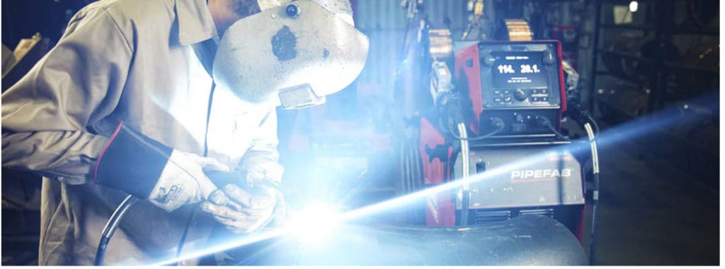
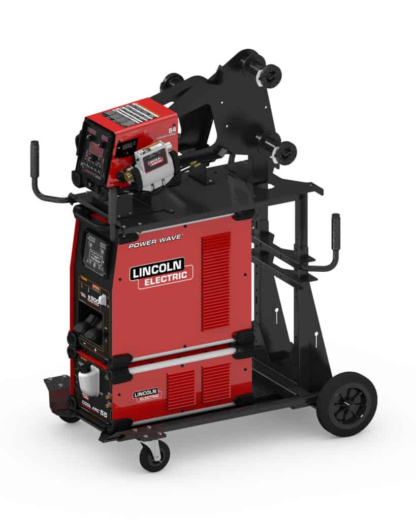
Lincoln Electric introduce the new PIPEFAB™ welding system
November 19, 2020 in Articles
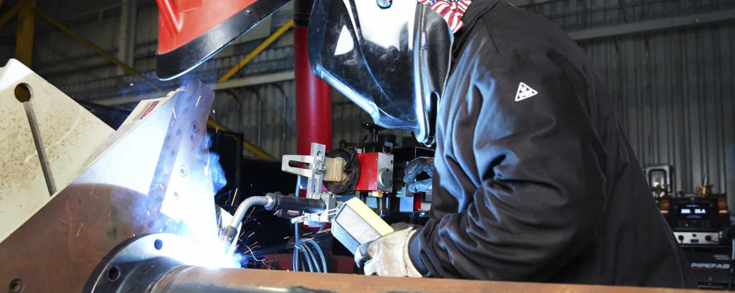
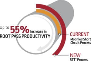
Pipe fabrication shops are looking for decreased welding times and more welded joints per day. This machine gives you ultimate savings and profits from your mild steel or stainless steel process pipe welding. More production output and faster completion time leads to significant cost savings. The new PIPEFAB™ welding system from Lincoln Electric is the ideal setup for pipe and vessel fabrication. Increasing your speed and productivity by up to 51%.
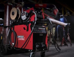
From concept to reality, the PIPEFAB™ welding system was developed for one purpose – to deliver the ideal setup for pipe and vessel fabrication. From machine design to arc performance, no detail was overlooked in delivering a complete, customer-driven system that lets your shop focus on what matters most – making high-quality root-to-cap welds, faster and easier.
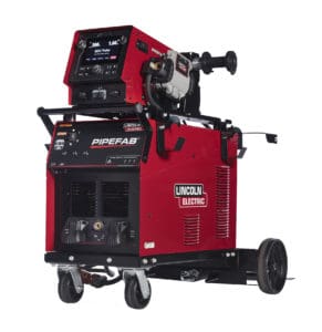
The PIPEFAB™ features game-changing performance and simplicity. Breakthrough arc performance – from root, to cap, to final fit – the PIPEFAB™ system has you covered with weld modes that have been fine-tuned to deliver breakthrough arc performance specifically for pipe and vessel fabrication. Industry-driven design – like the name says, the PIPEFAB™ system was developed specifically for pipe and vessel fabrication. With its Ready-to-Run™ design, every detail was considered in creating the ultimate setup for the pipe and vessel industry. Ready-to-Run™ design keeps all process outputs electrically isolated and ready to weld when needed – meaning you’ll never have to swap cables to change processes again. Straightforward and simple – Developed to be the fastest, smartest, and easiest solution on the market, the PIPEFAB™ system delivers straightforward and simple digital control with one-click process selection. Based on our successful Power Wave machines, the PIPEFAB system allows you to control welding as a process (implement, control and verify).
The PIPEFAB™ system’s display was designed, evaluated, and tested to deliver one thing – machine interaction that is as simple as possible. Lincoln wants you to weld more, worry less the PIPEFAB™ system helps maximise arc time and allow operators of all skill levels to focus more on making great welds. With one-button process changes, straightforward, easy-to-understand navigation, memory buttons for preferred settings, ArcFX® technology for visual arc settings feedback and single point of use – all controls in one location on the feeder.
 0
0
The intelligence has been built in. All PIPEFAB™ systems come ready to connect to powerful, yet simple-to-use software for configuration, updates and weld data monitoring. Including remote diagnostics and configuration, free and easy software updates – never worry about swapping or storing memory cards and CheckPoint® Production Monitoring. The PIPEFAB™ welding system is Industry 4.0 ready. Whether you are a pipeline contractor, mechanical contractor, vessel shop or general welding shop you want to maximise your pipe-inches made per day per welder.
Trusted expertise and support – Whatever challenge you may have Lincoln Electric is here to help with proven industry knowledge and support.
For more information or a demonstration visit the Lincoln Electric website.
by Graham Fry
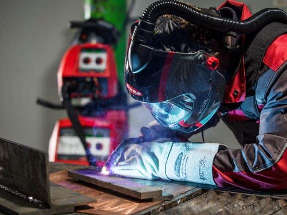
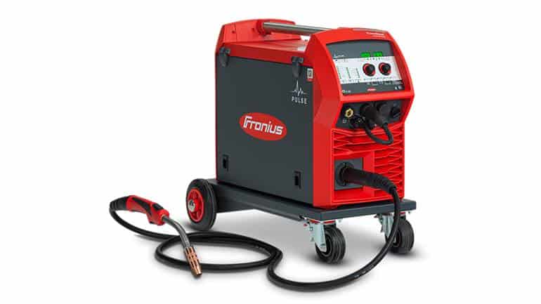
Pulse welding with Fronius TransSteel Pulse
November 19, 2020 in Articles
Up to 70% less rework
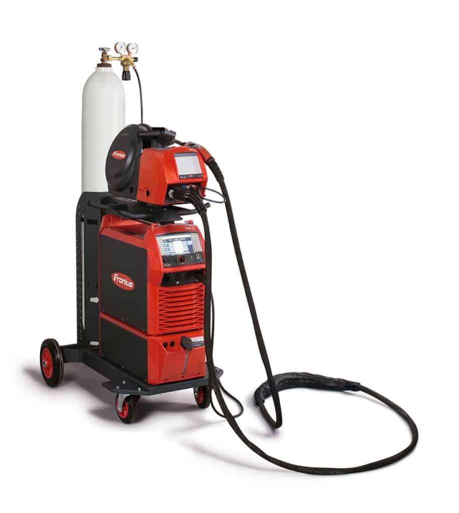
Fronius is upgrading its TransSteel series with the addition of the pulse function. Not only does the pulsed arc allow faster welding speeds on thicker materials, but rework is reduced as the pulsed arc causes less welding spatter.
The pulse mode makes it possible to bypass the intermediate arc, which is difficult to control and prone to spatter. The resulting reduction in spattering leads to up to 70% less rework. Furthermore, the pulsed arc allows welding speeds that are up to 30% higher to be achieved. All these advantages are now also available from the Fronius TransSteel 3000 compact as well as the TransSteel 4000 and 5000.
Pulse tacking to avoid distortion
The TransSteel devices were developed especially for use on steel. The addition of the pulse function now makes these power sources true all-rounders, as a wide range of functions supports the welder in various applications. With the help of the spot function, even and consistent welding spots can be produced – ideal for tacking workpieces. Interval welding not only produces a rippled seam appearance, but the lower heat input also reduces the possibility of material distortion on light gage sheets.
Special characteristics ensure the user has the ideal arc properties at their disposal. The “Steel” universal characteristics are particularly suitable for simple and fast welding applications. “Steel Root” has been developed for root welding and also provides a soft and stable dip transfer arc for good gap-bridging ability over wide gaps. The “Steel Dynamic” welding program, on the other hand, produces a particularly hard and concentrated arc, thus achieving high welding speeds and deep penetration. Where minimal spattering and deep penetration are the order of the day, the TransSteel Pulse models with “Pulse Controlled Spray Arc” provide the perfect settings. With the “SynchroPulse”, the welding power alternates between two operating points at a frequency of up to 5 Hertz. As the change between high and low current facilitates welding in a vertical up position, for example, it is possible to produce a pronounced seam rippling on aluminium alloys.
Three power categories, two models, one solution
The intuitive operating concept of the TransSteel allows immediate commissioning of the device without any previous knowledge. All the necessary welding parameters can be set on the front panel. A simple option for documenting the welding data completes the device concept. A USB thumb drive can be connected to the rear of the power source to store all important data – including time and device-related data, but also the parameters used such as current, voltage, and wire speed.
Fronius has added the pulse function to three models. The TransSteel 3000 compact Pulse is a multiprocess device that masters all three welding processes to the same high degree. The compact unit is ideal for a wide range of welding tasks on the construction site, in the workshop, or for repair work. For recurring welding tasks or in small series production, the pulse function on the TransSteel 4000 Pulse and TransSteel 5000 Pulse brings more options and speed. In contrast to the Compact version, these higher-power units have a separate wirefeeder.
If you would like to learn more about the Fronius TransSteel Pulse, visit the Fronius website.
by Graham Fry
2020 Kemppi “Art of Welding” Competition
July 28, 2020 in Articles
What can you do with a welding torch and some metal?
If you’re a Picasso with the welding tools then this competition is for you!
Kemppi is running an exciting competition for anyone involved in the “art of welding”. They want to see your best creation and have some valuable prizes to give away.
Find out more about this competition by downloading the flyer below.

by Graham Fry
Exploring the new Flexlite GX torch range from Kemppi
January 28, 2020 in Articles
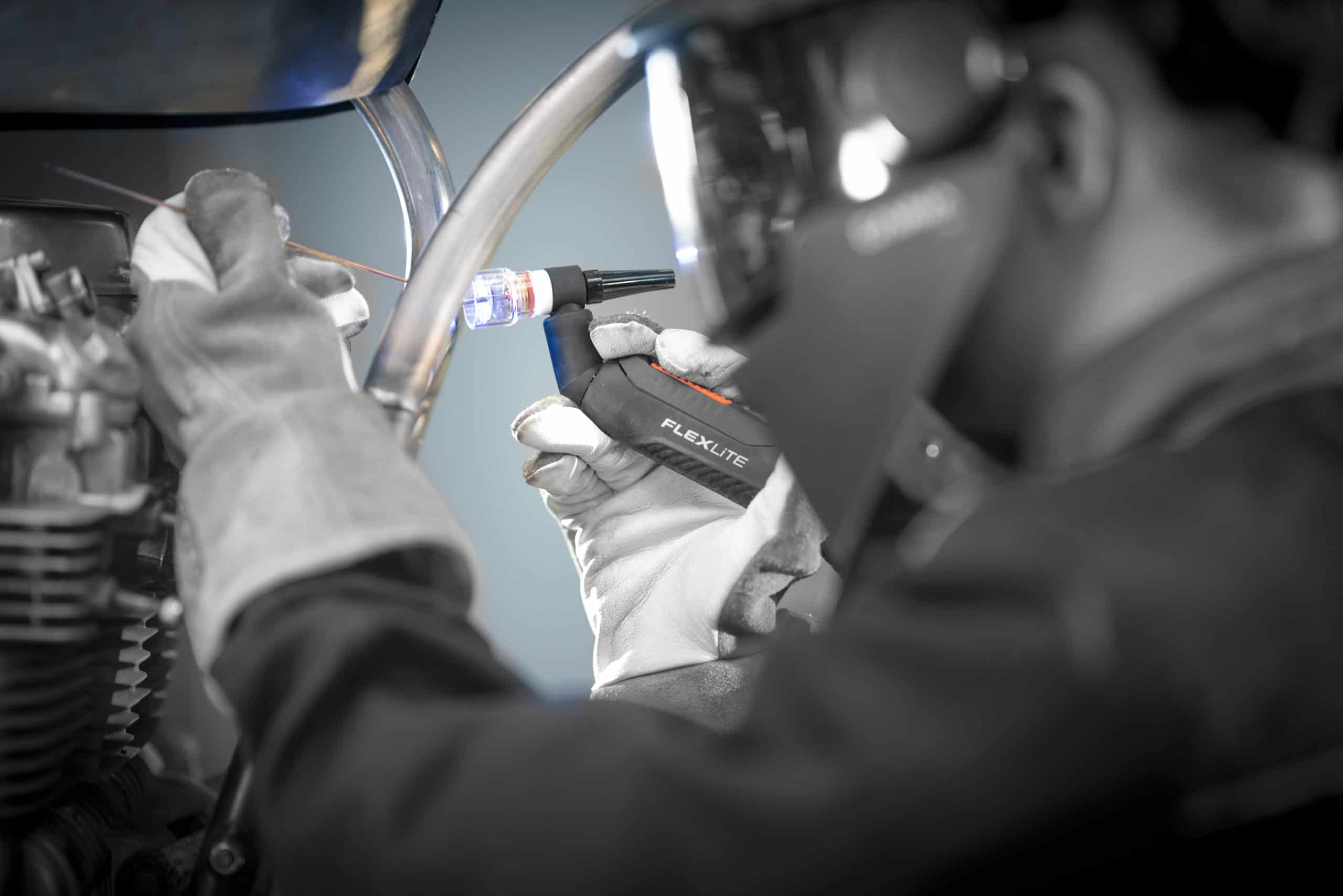
Kemppi’s new, high-performing Flexlite GX torch range delivers on ease and efficiency
Leading international welding equipment manufacturer, Kemppi, will shortly release its new Flexlite GX torches for MIG/MAG welding. Designed for comfort, reliability, performance and efficient use of consumables. Where previous torches are costly to use and maintain, the new Kemppi Flexlite GX welding torches, will help users increase productivity while saving on inventory costs.
Together with the Flexlite TX range for TIG welding, the Flexlite GX torches deliver next-generation capability for professionals and complete the Kemppi Flexlite family.
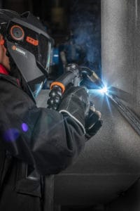
High-performance Torches
Built to perform under extreme temperatures and in demanding environments, the Flexlite GX range delivers quality welds. The sophisticated torches use power source capacity efficiently and help users create smooth and spatter free welds.
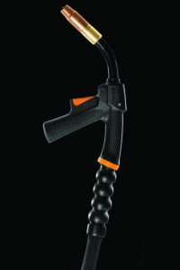
The shielding gas channels in the Flexlite GX gun have been separated and the cooling circulation runs to the very end of the gun neck. This keeps the neck gun cooler and enables cleaner welds, less spatter and reduced shielding gas consumption.
In addition, the innovative neck cooling system of the Flexlite GX series ensures that the temperature of the contact tip is up to 35% lower when compared to other corresponding welding guns. This benefits of this are:
- extending the life of the contact tip
- extending consumables life
- reducing costs
- making spare parts management easier
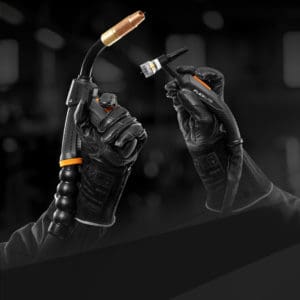
Excellent Ergonomics
The Flexlite GX torches also deliver comfort in spades and help reduce welder fatigue thanks to their ergonomic design. Each torch is lightweight and features a flexible cable set and innovative ball-jointed cable protection that reduces the load on the welder’s wrist.
Plus, the pistol grip handle has been anatomically designed so that it feels like an extension of the welder’s hand. Providing excellent balance, it allows for a natural wrist position. This makes the work at hand easier and more effortless, particularly when doing long welds. It also allows the welder to concentrate on challenging tasks rather than challenging equipment.
Less Parts, Lower Costs
The number of changeable parts in the Flexlite GX torches has been reduced by improving cross-matching across corresponding models, and by combining the functions of some of the consumables. The use of fewer parts reduces inventory costs so that welders can save on consumable costs.
Easy Access to Information
Every Flexlite GX welding torch and gun is equipped with a Quick Response code (QR) that quickly helps users find the right parts and accessories. Simply scan the QR code on your smart phone to access the information needed.
Wide, Quality Range
Made from high-quality materials, the Flexlite GX range is strong, robust and easy to operate. The range is available in three value levels: K3, K5 and K8. Each level is designed to serve specific welding needs. The torches are offered in alternate power classes and lengths, and in varying neck versions. On-torch remote controls are also available as optional accessories.
For more information on the new Flexlite GX torches call Kemppi Australia on (02) 8785 2000 or email sales.au@kemppi.com or visit the Kemppi website.
by Graham Fry
2019 in review
December 20, 2019 in Articles
This year the Australian Welding Institute has experienced significant growth. Our membership has increased by 20% and WeldED subscribers have increased by 41%. We take great pride in being able to provide networking opportunities for our members. We have formed an accepting community of welding professionals who have exchanged knowledge and formed lasting connections. AWI’s is growing as more members became actively involved with our institute for the betterment of welding in Australia.
The welding industry saw a busy start to the year, particularly in the mining, infrastructure and defence sectors. Road and rail infrastructure remained a strong source of opportunity for the Australian welding industry with many projects continuing to arise across the nation. There are promising signs that oil and gas mining may be returning as a viable industry next year providing new job opportunities. AWI is optimistic about the coming year and strongly believe it will be a successful year for the industry. In these challenging times, it’s imperative that we continue optimising welding processes through automation, mechanism and staff training.
Thank you to all who provided their feedback by completing our inaugural member survey. We had an overwhelming response to the survey and are working to implement the many constructive ideas that were suggested to us. Your responses have helped the board identify what’s working well and where the specific areas for improvement are. We are constantly working towards improving the member experience and have some exciting changed coming in 2020!
We’d like to thank our members and sponsors for their continued support. We wouldn’t be able to do what we do without you and look forward to providing more resources and opportunities for the welding industry in the new year.
by Graham Fry
A general review of geometric shape imperfections – Fillet welds
December 20, 2019 in Articles
So far in this welding expertise article, we’ve covered welding imperfections such as cracks, lack of fusion, incompletely filled grooves and root concavity, among other imperfections.
This third and final instalment is all about the imperfections that occur with fillet welds and how to avoid them.
This article will specifically focus on:
- Excessive convexity
- Oversized fillet welds
- Undersized fillet welds
- Asymmetric fillet welds
- Poor fit-up
Excessive convexity
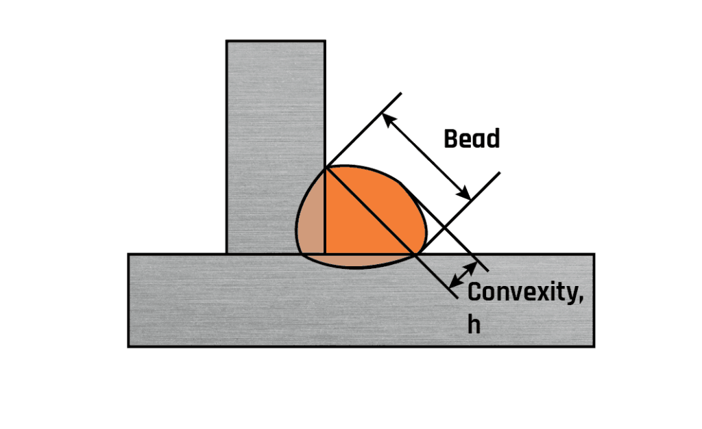
Fig 1. Excessive convexity
This feature is also covered by the definition for excess weld metal (see Part 1) and may be described as weld metal lying outside the plane joining the weld toes. Note that the term ‘reinforcement’, although used extensively in the ASME/AWS specifications is avoided in Europe as it implies that excess metal contributes to the strength of the welded joint. This is rarely the case.
Common causes
Poor technique and the deposition of large volumes of ‘cold’ weld metal.
Acceptance
The idealised design requirement of a ‘mitre’ fillet weld is often difficult to achieve, particularly with manual welding processes.
BS EN ISO 5817 acceptance is based on a mitre fillet weld shape with a specific design throat and any excess weld metal is measured in relation to this mitre surface. The limits for this imperfection relate the height of the excess metal to the width of the bead with maximum values ranging from 3mm for a stringent quality level to 5mm for a moderate quality level. Surprisingly, there is no reference to a ‘smooth transition’ being required at the weld toes for such weld shape.
AWS D1.1 also has limits relating width to acceptable excess as follows:
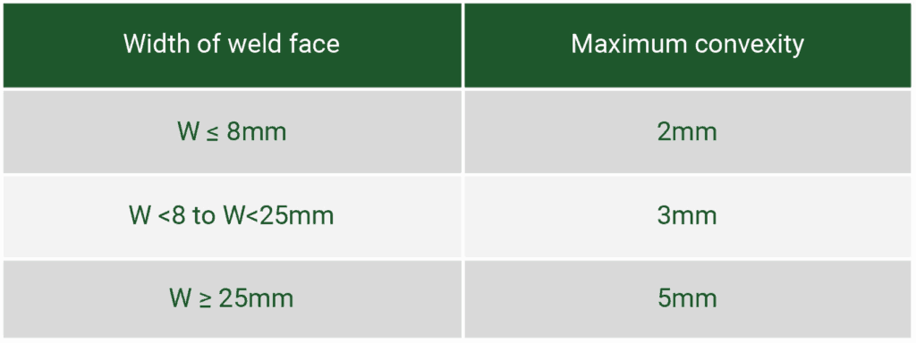
Avoidance
Welder technique is the major cause of this problem and training may be required. It is also important to ensure that the parameters specified in the welding procedures specification are adhered to.
Oversize fillet welds (welds with a throat larger than required by the design)
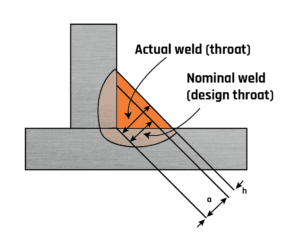
Fig 2. Oversize fillet weld
As discussed previously, oversized fillet welds can represent a significant additional cost and loss of productivity.
Common causes
There are some welding-related causes, eg high welding current, slow travel speeds, and some supervision related (eg ‘to be safe make this fillet bigger by x mm’).
Acceptance
BS EN ISO 5817 has limits related to the actual throat (eg for stringent quality levels, the actual weld throat [a] may exceed the nominal (design) weld throat [h] by 1+0.15a with a maximum of 3mm. For the moderate quality level (D) the excessive throat thickness is unlimited.
Avoidance
Adhere to the specified welding procedure and parameters and do not add to the specified weld size. Where possible mechanise the welding operation.
Undersized fillet welds (fillet welds smaller than those specified)
Undersized fillet weld
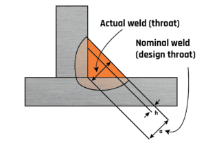
Fig.3. Undersized fillet weld
Common causes
The welding-related causes are associated with high welding speeds and low welding currents.
Acceptance
Therefore, it is normally assumed that fillet welds will be at least of the size specified. BS EN SIO 5817 states that limits to insufficient throat thickness are not applicable to processes with proof of greater depth of penetration, therefore a fillet weld with an apparent throat thickness smaller that that prescribed should not be regarded as being imperfect if the actual throat thickness with a compensating greater depth of penetration complies with the nominal value. That is if we can be sure there is good penetration the smaller fillet may be acceptable, however, this should be discussed with the designer of the fabrication. The limits set by the standard.
Relying upon deep penetration to provide the required minimum design throat thickness can be difficult to justify. Penetration is a weld characteristic that is hard to measure directly and reliance must be placed on the stringent control of both the welding process and the welder. Manual welding can rarely be relied upon to provide the required consistency but it is an option with mechanised welding systems.
Avoidance
Adhere to the specified welding procedure and parameters. Use sufficient current and appropriate travel speed. Where possible mechanise the welding operation.
Asymmetric fillet weld (a fillet weld where the legs are of unequal length)
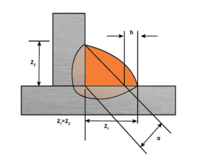
Fig 4. Asymmetric fillet weld (a fillet weld where the legs are of unequal length)
Common causes
Due to incorrect electrode positioning or to gravity pulling the molten pool towards one face of the joint. It is an mainly a problem with fillet welds made in the horizontal/vertical (PB) position.
Acceptance
There are instances where asymmetry may be specified (eg to place the toe stress concentration in a particular region).
BS EN ISO 5817 would, for a 10mm leg length fillet weld (ie 7.1mm throat) allow a difference in leg lengths of about 2.5mm at the stringent quality level and 3.4mm at the moderate quality level. Acceptance is related to throat thickness.
The consequence of this imperfection is a significant increase in weld volume. Provided the leg length requirement is achieved there would not be a loss of strength. Perhaps this is why, in other standards, a requirement is not specified and the acceptability is left to the inspection personnel to make the ‘engineering judgement’.
Poor fit-up
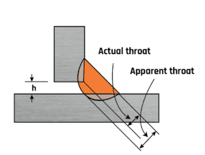
Fig 5. Poor fit-up
The most common imperfection is an excessive gap between the mating faces of the materials.
Common causes
Poor workshop practice, poor dimensioning and tolerance dimensions on drawings.
Acceptance
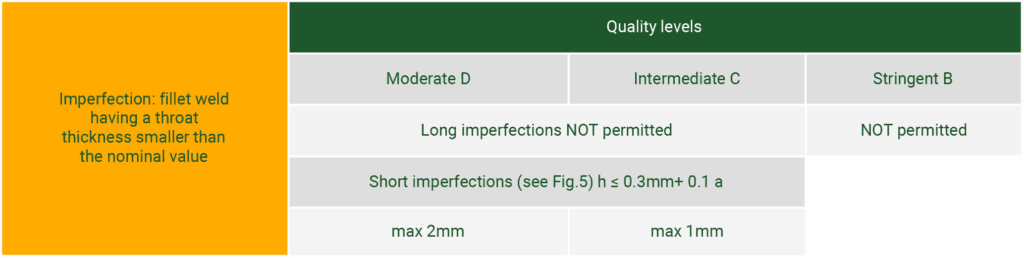
A major problem with fillet welds is ensuring the gap between the components is within defined limits. BS EN ISO 5817 specifies the acceptance criteria as follows:
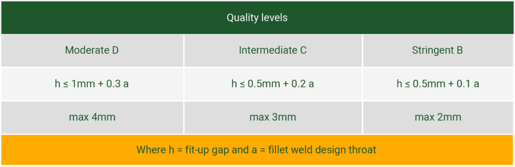
Where h = fit-up gap and a = fillet weld design throat
Figure 5 shows that the gap results in a reduction in the leg length on the vertical plate and this, in turn, results in a reduction in the throat thickness of the joint. A 10mm leg length fillet with a root gap of 3mm gives an effective leg of 7mm (a throat of 4.9mm instead of the expected 7mm).
When the application of BS EN ISO 5817 is not required, the guidance of BS EN 1011-2 can be followed, which recommends a maximum gap of 3mm. This standard also states that the size of the fillet weld can be increased to compensate for a large gap.
This discrepancy is addressed within AWS D1.1. which permits a root gap of up to 5mm for material thickness up to 75mm. However, ‘if the (joint) separation is greater than 2mm the leg of the fillet weld shall be increased by the amount of the root opening, or the contractor shall demonstrate that the effective throat has been obtained’.
This article was originally published in Connect, January 2004. It has since been updated and this web page no longer reflects exactly the printed version.
by Graham Fry
Weld Imperfections that lead to poor geometric shape
November 27, 2019 in Articles
In part one of this expert welding knowledge series, welding imperfections such as cracks, lack of fusion, penetration and porosity were discussed. This article looks at how common welding imperfections relate to the poor geometric shape of welds.
This article will concentrate on the following:
- Incomplete filled groove
- Excessive penetration
- Root concavity
Incomplete filled groove
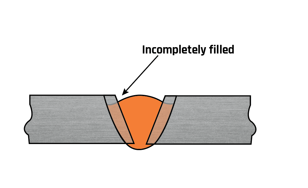
This is a continuous, or intermittent, channel in the surface of a weld, running along its length, due to insufficient weld metal.
Common causes
This problem arises when there has been insufficient filler metal (current or wire feed too low or too high a travel speed) so that the joint has not been sufficiently filled. The result is that the thickness of weldment is less than that specified in the design, which could lead to failure.
Acceptance
Most standards will not accept this type of imperfection, except perhaps over short lengths and even then a smooth transition is required. The designer expects the joint to be adequately filled, but not too much so (see excess weld metal).
Often the presence of this imperfection is an indication of poor workmanship and could suggest that further training is required.
Excessive penetration (Excess penetration bead)
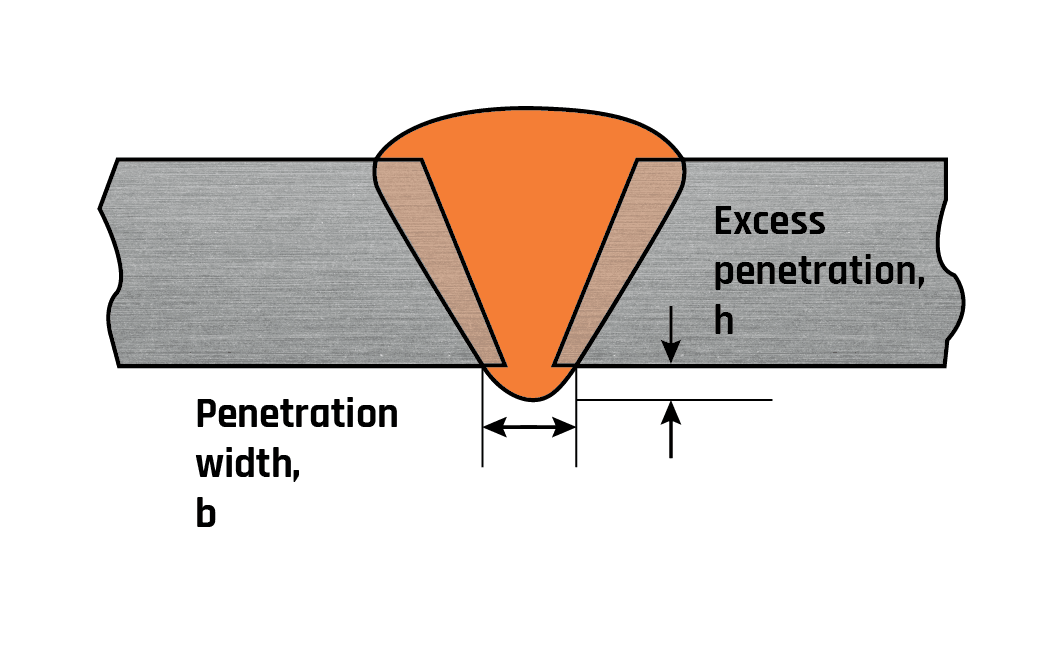
Excess weld metal protruding through the root of a fusion (butt) weld made from one side only.
With pipe welding, this type of imperfection may cause effects in the fluid flow that can cause erosion and/or corrosion problems.
Common causes
Penetration becomes excessive when the joint gap is too large, the root faces are too small, the heat input to the joint is too high or a combination of these causes.
Acceptance
The criteria that set the level of acceptable penetration depends primarily on the application code or specification.
BS 2971 (Class 2 arc welding) requires that the ‘penetration bead shall not exceed 3mm for pipes up to and including 150mm bore or 6mm for pipes over 150mm bore’.
BS 2633 (Class 1 arc welding) gives specific limits for smaller diameters pipes, eg for pipe size 25-50mm the maximum allowed bore penetration is 2.5mm.
ASME B31.3 bases acceptability on the nominal thickness of the weld, for instance, allowing for a thickness range of 13-25mm up to 4mm of protrusion. However, ASME notes that ‘more stringent criteria may be specified in the engineering design’.
BS EN ISO 5817 (Quality levels for imperfections), which supersedes BS EN 25817, relates the acceptable protrusion to the width of the under-bead as follows:
| Severity of service | Moderate, D | Stringent, B |
| Limit (up to maximum) | h ≤ 1mm + 1.0 b | h ≤ 1mm + 0.2 b |
| Maximum | 5 mm | 3 mm |
| For thicknesses > 3mm where: h = height of excess & b = width of root (see Fig.1) | ||
Avoidance
It is important to ensure that joint fit-up is as specified in the welding procedure. If welder technique is the problem then retraining is required.
Root concavity (suck-back; underwashing)
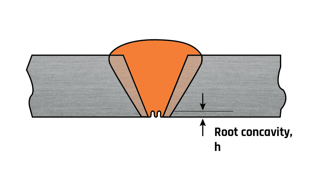
A shallow groove that may occur in the root of a butt weld.
Common causes
Root concavity is caused by shrinkage of the weld pool in the through-thickness direction of the weld. Melting of the root pass by the second pass can also produce root concavity.
This imperfection is frequently associated with TIG welding with the most common cause being poor preparation leaving the root gap either too small or, in some cases, too large. Excessively high welding speeds make the formation of root concavity more likely.
Acceptance
The root concavity may be acceptable. This will depend on the relevant standard being worked to. For example:
BS 2971 requires that:
a) there is complete root fusion
b) the thickness of the weld is not less than the pipe thickness.
ASME B31.3 requires that the ‘total joint thickness, including weld reinforcement, must be greater than the weld thickness’.
BS EN ISO 5817 sets upper limits related to the quality level, eg for thicknesses > 3mm Moderate, (D), h ≤ 0.2t but max 2mm for Stringent, (B), h ≤ 0.05t but max 0.5mm. Furthermore, a smooth transition is required at the weld toes.
In effect, the standards require that the minimum design throat thickness of the finished weldment is achieved. If the first two conditions of acceptance are met but the weld face does not have a sufficiently high cap, additional weld metal may be deposited to increase the throat.
Avoidance
It is important to ensure that joint fit-up is as specified in the welding procedure and that the defined parameters are being followed. If the welder technique is the problem then retraining is required.
Stay tuned for the third and final part of this series as we discuss the geometric shape imperfections of fillet welds.
by Graham Fry
The Seven Most Common Welding Defects, Causes and Remedies
November 27, 2019 in Articles
Defects are common in any type of manufacturing, welding included. In the process, there can be deviations in the shape and size of the metal structure. It can be caused by the use of the incorrect welding process or the wrong welding technique. Learn about the 7 most common welding defects, their types, causes and remedies, below.
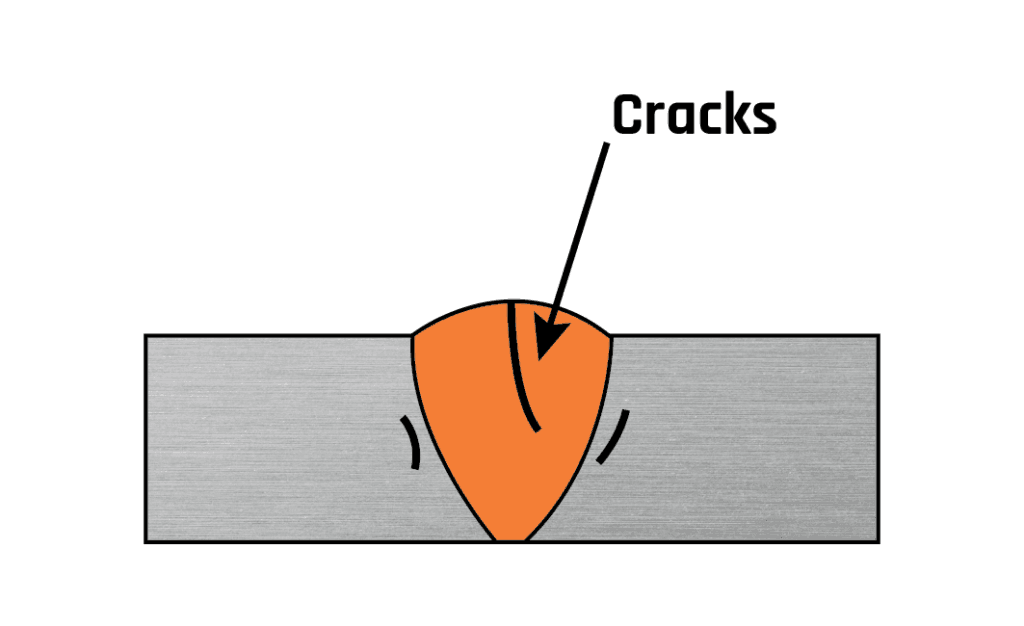
Weld Crack
The most serious type of welding defect is a weld crack and it’s not accepted almost by all standards in the industry. It can appear on the surface, in the weld metal or the area affected by the intense heat.
There are different types of cracks, depending on the temperature at which they occur:
Hot cracks
These can occur during the welding process or during the crystallization process of the weld joint. The temperature at this point can rise over 10,000C.
Cold cracks
These cracks appear after the weld has been completed and the temperature of the metal has gone down. They can form hours or even days after welding. It mostly happens when welding steel. The cause of this defect is usually deformities in the structure of steel.
Crater cracks
These occur at the end of the welding process before the operator finishes a pass on the weld joint. They usually form near the end of the weld. When the weld pool cools and solidifies, it needs to have enough volume to overcome shrinkage of the weld metal. Otherwise, it will form a crater crack.
Causes of cracks:
- Use of hydrogen when welding ferrous metals.
- Residual stress caused by the solidification shrinkage.
- Base metal contamination.
- High welding speed but low current.
- No preheat before starting welding.
- Poor joint design.
- A high content of sulfur and carbon in the metal.
Remedies:
- Preheat the metal as required.
- Provide proper cooling of the weld area.
- Use proper joint design.
- Remove impurities.
- Use appropriate metal.
- Make sure to weld a sufficient sectional area.
- Use proper welding speed and amperage current.
- To prevent crater cracks make sure that the crater is properly filled.
Porosity
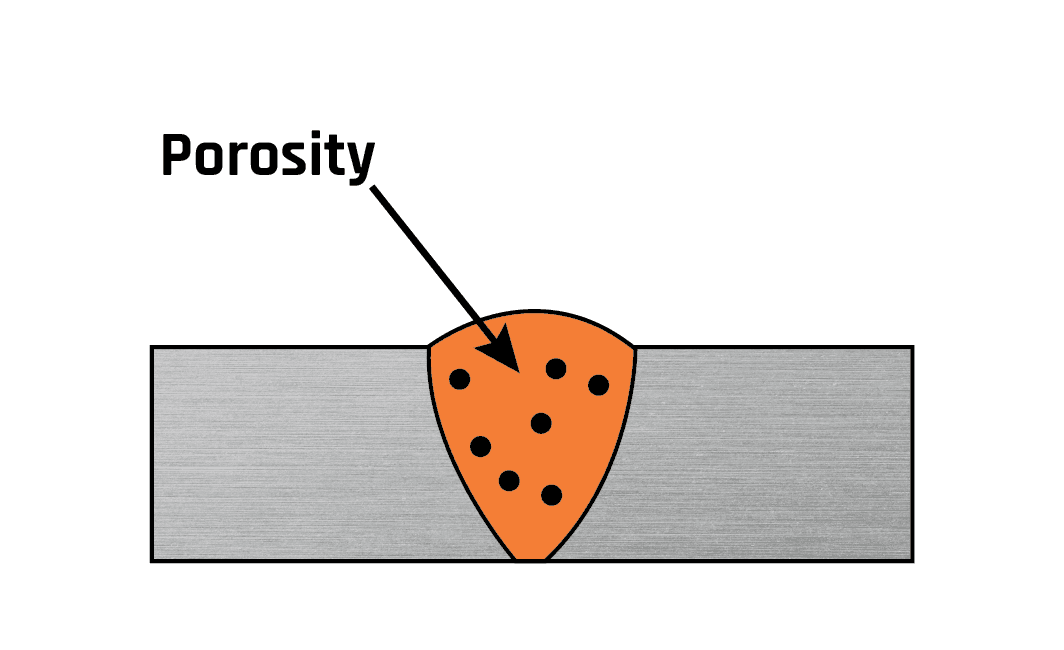
Porosity occurs as a result of weld metal contamination. The trapped gases create a bubble-filled weld that becomes weak and can with time collapse.
Causes of porosity:
- Inadequate electrode deoxidant.
- Using a longer arc.
- The presence of moisture.
- Improper gas shield.
- Incorrect surface treatment.
- Use of too high gas flow.
- Contaminated surface.
- Presence of rust, paint, grease or oil.
Remedies:
- Clean the materials before you begin welding.
- Use dry electrodes and materials.
- Use correct arc distance.
- Check the gas flow meter and make sure that it’s optimized as required with proper with pressure and flow settings.
- Reduce arc travel speed, which will allow the gases to escape.
- Use the right electrodes.
- Use a proper weld technique.
Undercut
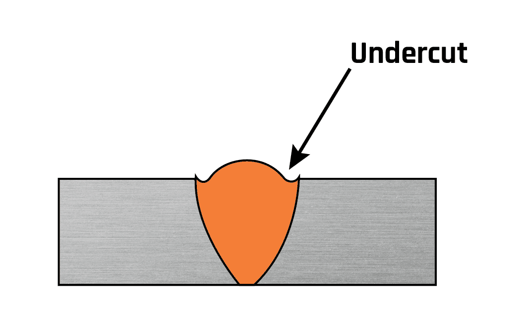
This welding imperfection is the groove formation at the weld toe, reducing the cross-sectional thickness of the base metal. The result is the weakened weld and workpiece.
Causes:
- Too high weld current.
- Too fast weld speed.
- The use of an incorrect angle, which will direct more heat to free edges.
- The electrode is too large.
- Incorrect usage of gas shielding.
- Incorrect filler metal.
- Poor weld technique.
Remedies:
- Use proper electrode angle.
- Reduce the arc length.
- Reduce the electrode’s travel speed, but it also shouldn’t be too slow.
- Choose shielding gas with the correct composition for the material type you’ll be welding.
- Use of proper electrode angle, with more heat directed towards thicker components.
- Use of proper current, reducing it when approaching thinner areas and free edges.
- Choose a correct welding technique that doesn’t involve excessive weaving.
- Use the multipass technique
Incomplete Fusion
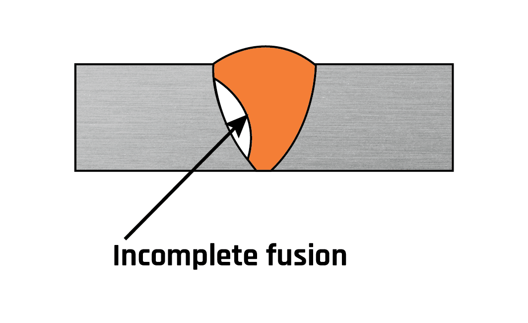
This type of welding defect occurs when there’s a lack of proper fusion between the base metal and the weld metal. It can also appear between adjoining weld beads. This creates a gap in the joint that is not filled with molten metal.
Causes:
- Low heat input.
- Surface contamination.
- Electrode angle is incorrect.
- The electrode diameter is incorrect for the material thickness you’re welding.
- Travel speed is too fast.
- The weld pool is too large and it runs ahead of the arc.
Remedies:
- Use a sufficiently high welding current with the appropriate arc voltage.
- Before you begin welding, clean the metal.
- Avoid molten pool from flooding the arc.
- Use correct electrode diameter and angle.
- Reduce deposition rate.
Incomplete Penetration
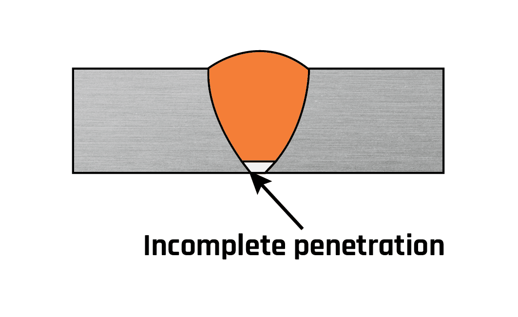
Incomplete penetration occurs when the groove of the metal is not filled completely, meaning the weld metal doesn’t fully extend through the joint thickness.
Causes:
- There was too much space between the metal you’re welding together.
- You’re moving the bead too quickly, which doesn’t allow enough metal to be deposited in the joint.
- You’re using a too low amperage setting, which results in the current not being strong enough to properly melt the metal.
- Large electrode diameter.
- Misalignment.
- Improper joint.
Remedies:
- Use proper joint geometry.
- Use a properly sized electrode.
- Reduce arc travel speed.
- Choose proper welding current.
- Check for proper alignment.
Slag Inclusion
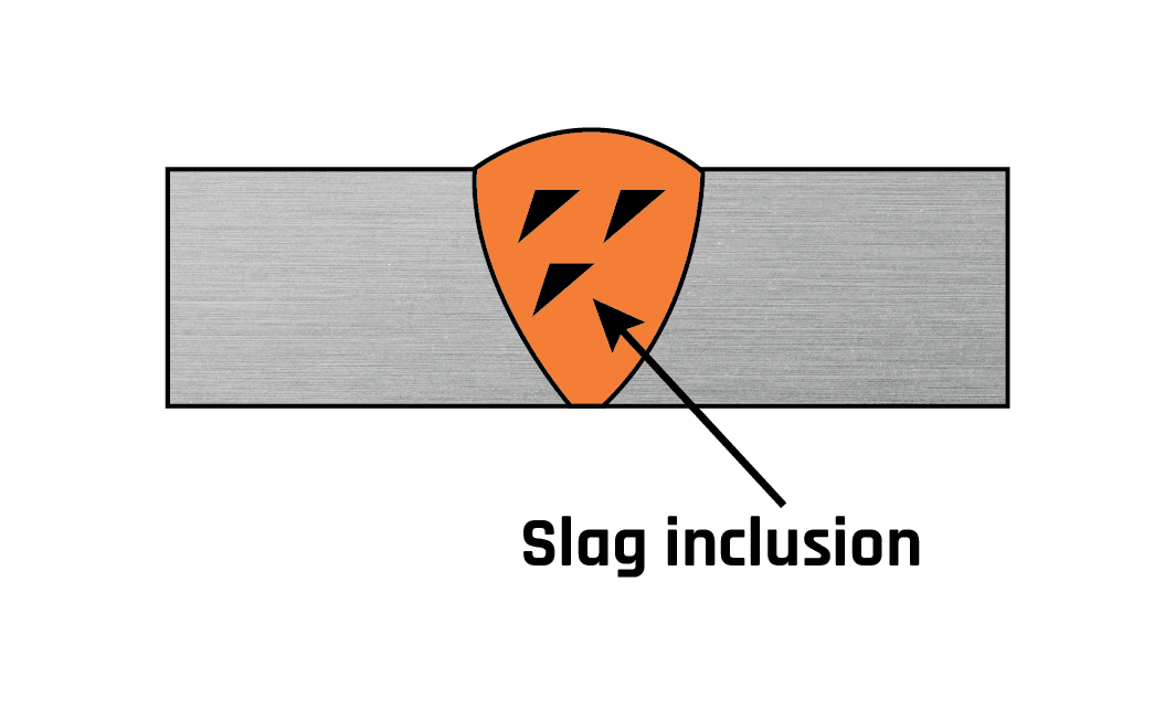
Slag inclusion is one of the welding defects that are usually easily visible in the weld. Slag is a vitreous material that occurs as a byproduct of stick welding, flux-cored arc welding and submerged arc welding. Is can occur when the flux, which is the solid shielding material used when welding, melts in the weld or on the surface of the weld zone.
Causes:
- Improper cleaning.
- The weld speed is too fast.
- Not cleaning the weld pass before starting a new one.
- Incorrect welding angle.
- The weld pool cools down too fast.
- Welding current is too low.
Remedies:
- Increase current density.
- Reduce rapid cooling.
- Adjust the electrode angle.
- Remove any slag from the previous bead.
- Adjust the welding speed.
Spatter
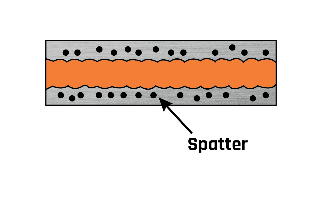
Spatter occurs when small particles from the weld attach themselves to the surrounding surface. It’s an especially common occurrence in gas metal arc welding. No matter how hard you try, it can’t be completely eliminated. However, there are a few ways you can keep it to a minimum.
Causes:
- The running amperage is too high.
- Voltage setting is too low.
- The work angle of the electrode is too steep.
- The surface is contaminated.
- The arc is too long.
- Incorrect polarity.
- Erratic wire feeding.
Remedies:
- Clean surfaces prior to welding.
- Reduce the arc length.
- Adjust the weld current.
- Increase the electrode angle.
- Use proper polarity.
- Make sure you don’t have any feeding issues.
When welding, the aim is to produce compliant welds, not perfect welds. Some discontinuities are allowed in compliant welds but too many will result in a defective weld. Ensure you pay attention to all variables to reduce inconsistencies and the risk of a defective weld.
by Graham Fry

Turn your trade into a teaching career
November 21, 2019 in Articles
Have you ever considered a career change but did not know where to start? Are you stuck in a dead-end job, or still looking for a way to reach your full potential? Then have you considered a career teaching technology in schools?
You may not yet know it, but today in Australia there is a chronic shortage of qualified Technology and Vocation Education and Training (VET) teachers in schools. Principals around the nation are crying out for teachers with the kind of technical knowledge and industrial experience that you probably take for granted. If you like the idea of working with young people and are curious to learn more about how you could turn your trade into a professional teaching career, then keep reading!
What is it?
The Bachelor of Technology Education course at La Trobe University is a specialist qualification unlike any other. It is the only University course that actively seeks and recruits experienced tradespeople for the specific purpose of preparing them to become qualified and registered school teachers in Victoria. Traditionally, tradespeople have faced significant barriers to entering Higher Education, which is something that makes this course particularly unique. At La Trobe, we value trade qualifications and industrial experience so much so, that we offer our students a massive two years of advanced standing (of a four-year teaching degree). In other words, for everyone accepted into the course, their study commitment is reduced by half.
What’s involved?
The course itself was originally designed with mature tradespeople in mind. It has many features including:
- Two years advanced standing in recognition of trade qualification & industry experience
- Choice of full or part-time studies
- Mid-year entry
- Weekend classes (so you can keep your day job while studying towards a career change)
- Blended learning (part online and part face-to-face)
- Endorsed by AEU as meeting the 2108 TAFE Teacher Agreement (MEA)
- Scholarship opportunities
- Other tradespeople just like you!
What are the career opportunities?
Students in this course are highly sort after by both TAFEs and secondary schools – to the point where the vast majority of our students are employed as teachers (in TAFE or on Permission to teach from the Victorian Institute of Teaching) before they even graduate. Today, trade qualified and industry experienced teachers are like gold-dust to secondary schools who currently struggle to equip their students with the technical know-how they need to prepare for their future careers and livelihoods.
If you have reached that point in life where you may be considering a change of pace, ready to move on to a rich and rewarding career that benefits yourself as well as the community, then maybe teaching is just opportunity you have been waiting for.
If you would like to know more about the Bachelor of Technology Education course, contact Karen at k.oreilly-briggs@latrobe.edu.au or call 03 9479 1325.
Dr Karen O’Reilly-Briggs is a trade qualified Metal Fabricator and AS1796 Pressure vessel welder, CSWIP Welding Inspector, AWI member, and the Course Coordinator of the Bachelor of Technology Education program at La Trobe University, Bundoora VIC.

by Graham Fry
Benefits of HyperFill versus Single Wire
October 25, 2019 in Articles
HyperFill is two wires or twin wires that use the exclusive Lincoln pulse waveform technology to bring them together as one arc. The innovative twin wire design delivers a wide, evenly-distributed arc cone that allows for higher deposition rates – on average 50% higher deposition than a single wire – without compromising the weld quality or ease-of-use. This translates to a reduced number of hours spent welding a structure, which in turn, translates to more profit.
The HyperFill arc cone produces a smooth, stable puddle that is more favourable for the weld and makes the process easy to use at high deposition rates. The wide arc cone also leads to a more favourable and robust penetration profile, improving the weld quality at high deposition rates.
Importantly, a manual welder skilled in single arc welding does not need to be retrained to adapt to using HyperFill and the technology can be welded by either a welding robot or human fabricator.
HyperFill was created to provide robotic-type deposition rates and put those deposition rates into the hands of the manual welder. At the same time, we wanted to keep the system simple to set up and operate. HyperFill welding techniques are the same as standard MIG welding, so no retraining is required. There is one power source, one water cooler, one feeder and a twin welding tip. The welding torch is water-cooled to keep it light in weight and cool to the hands.
Furthermore, the HyperFill technology can be used with multiple wires: solid wires, metal-cored wires or flux-cored wires. It adds on to Lincoln’s existing Power Wave multi-process welders and therefore harnesses the range of benefits that these machines provide as well.
Increase your productivity
The new HyperFill twin wire technology available through Lincoln Electric enables welding fabricators within the structural, mining and heavy fabrication sector to significantly increase their welding productivity without compromising on quality. Easy-to-use, this add-on to existing Power Wave S500 and S700 welding machines, provides manual welders with robotic deposition rates that allows them to weld structures in faster timeframes. HyperFill is a cost-effective solution to the series of challenges that single wire MIG welding presents to fabricators in this industry.
For more information visit: www.lincolnelectricsolutions.com.au
Watch this demo video: https://www.youtube.com/watch?v=WmFnhCHCr98
by Graham Fry
A General Review of Geometric Shape Imperfections – Types and Causes
October 25, 2019 in Articles
In the job knowledge series welding imperfections such as cracks, lack of fusion, penetration and porosity have been discussed. This article looks at those imperfections related to poor geometric shape and will concentrate on the following:
- Excess weld metal
- Undercut
- Overlap
- Linear misalignment
- Incompletely filled groove
Such imperfections might be considered as anomalies in the joint and they will always be present to some degree so that it becomes necessary to separate the acceptable from the unacceptable. This is done by following guidance given by the application standard, which was the basis for the component design, and/or by direction, as set out in the job contract. Examples of standards that might be referred to are:
- PD 5500 Specification for unfired fusion welded pressure vessels.
- BS EN ISO 5817 Welding. Fusion-welded joints in steel, nickel, titanium and their alloys (beam welding excluded). Quality levels for imperfections
- AWS D1.1 Structural welding code – Steel
Excess weld metal
(also called cap height, overfill or reinforcement)
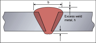
Fig.1. Excess weld metal
This is weld metal lying outside the plane joining the weld toes. Note that the term ‘reinforcement’, although used extensively in the ASME/AWS specifications is avoided in Europe as it implies it adds strength to the welded joint, which is rarely the case.
Common causes
This imperfection is formed when excessive weld metal is added to the joint, which is usually a result of poor welder technique for manual processes but may be due to poor parameter selection when the process is mechanised. That is, too much filler metal for the travel speed used. In multi-run welding a poor selection of individual bead sizes can result in a bead build-up pattern that overfills the joint. Different processes and parameters (eg voltage) can result in different excess weld metal shapes.
Acceptance
The acceptability of this imperfection is very dependent on the application in which the product will be used. Most standards have limit, related to material thickness (eg 10%), but also have a maximum upper limits. Both the ratio and the maximum may be related to the severity of service that the component is expected to see. The following table gives examples taken from BS EN ISO 5817.
| Excess weld metal limits for quality levels: | ||
| Severity of service | Moderate, D | Stringent, B |
| Limit (up to maximum) | h = 1mm + 0.25 b | h = 1mm + 0.1 b |
| Maximum | 10 mm | 5 mm |
| Transition required | smooth | smooth |
| Where: h = height of excess & b = width of bead (see figure 1) | ||
An important reason for limiting the height of excess weld metal is that it represents a non-value added cost. However, it must be remembered that the height of the weld cap influences the resultant toe blend. A sharp transition causes a local stress concentration that can contribute to loss of strength, which is particularly important in fatigue situations. As a result most specifications state that ‘smooth transition is required’.
Avoidance
If the imperfection is a result of welder technique then welder retraining is required. For mechanised techniques an increase in travel speed or voltage will help to reduce cap height.
Undercut
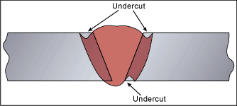
Fig.2. Undercut
This is an irregular groove at the toe of a run in the parent metal.
The figure shows undercut at surface of a completed joint but it may also be found at the toes of each pass of a multi-run weld. The latter can result in slag becoming trapped in the undercut region.
Common causes
When arc and gas welding, undercut is probably the most common shape imperfection. With single-sided pipe welds it may also be found at the bore surface. It may also be seen on the vertical face of fillet welds made in the horizontal vertical position.
A wide spreading arc (high arc voltage) with insufficient fill (low current or high travel speed) is the usual cause. However, welder technique, especially when weaving, and the way the welding torch is angled can both cause and be used to overcome undercutting (ie angled to push the weld metal to fill the melted groove). High welding current will also cause undercut – this is generally associated with the need for a high travel speed to avoid overfilling of the joint.
Acceptance
Largely because this imperfection is widespread, most standards permit some level of undercut although they do require that a ‘smooth transition is required. The limits in BS EN ISO 5817 range from 0.5mm (stringent) to 1mm (moderate) for thickness (t) greater than 3mm (more stringent limits are required for t 0.5 to 3mm), while AWS D1.1 has a limit of 1mm.
Measuring undercut can be a problem because of the small size of the imperfection compared with the general environment where there can be mill scale, irregularities in the surface and spatter.
In critical applications the imperfection can be ‘corrected’ by blend grinding or by depositing an additional weld bead.
Avoidance
This imperfection may be avoided by reducing travel speed and/or the welding current and by maintaining the correct arc length.
Overlap (cold lapping)
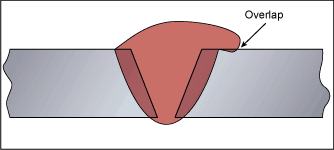
Fig.3. Overlap
This is an imperfection at a toe or root of a weld caused by metal flowing on to the surface of the parent metal without fusing to it. It may occur in both fillet and butt welds.
Common causes
This is often caused by poor manipulation of the electrode or welding gun, especially when the weld pool is large and ‘cold’, where the welder allows gravity to influence the weld shape before solidification. Tightly adherent oxides or scale on the metal surface can also prevent the weld metal fusing with the parent metal to cause the overlap imperfection.
Avoidance
Avoidance is achieved through an acceptable level of welder skill and a reduction in weld pool size (obtained by reducing current or increasing travel speed). Adequate cleaning of the parent plate is also important.
Acceptance
Standards rarely allow the presence of this imperfection, unless the length is short (eg BS EN ISO 5817 for moderate quality level D). Overlap can be very difficult to detect, especially if it is extremely small.
Linear misalignment
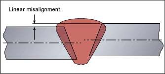
Fig.4. Linear Misalignment
(Also known in the USA as high-low).
This imperfection relates to deviations from the correct position/alignment of the joint.
Common causes
This is primarily a result of poor component fit-up before welding, which can be compounded by variations in the shape and thickness of components (eg out of roundness of pipe). Tacks that break during welding may allow the components to move relative to one another, again resulting in misalignment.
Acceptance
The acceptability of this defect is related to the design function of the structure or pipe line either in terms of the ability to take load across the misalignment or because such a step impedes the flow of fluid.
Acceptance varies with the application:
BS EN ISO 5817 relates misalignment to wall thickness but sets maximum limits (eg for material thickness t>3mm and moderate limits of imperfections D, = 0.25 x t, with a maximum of 5mm).
AWS D1.1 allows 10% of the wall thickness up to a maximum of 3mm.
The consequence of linear misalignment can, when welding is carried out from one side, be lack of root or sidewall fusion to give a sharp continuous imperfection along the higher weld face toe. In some situations linear misalignment in the bore of a pipe can lead to in-service problems where turbulence of the carrier fluid in the pipe creates subsequent erosion.
Stay tuned for part 2 in the November edition of WeldED!
by Graham Fry
Kemppi’s first-ever double-pulse TIG process
October 25, 2019 in Articles
Kemppi’s first-ever double-pulse TIG process is delivering considerable welding benefits for the welders who have used it thus far!
Developed by leading international welding equipment manufacturer, Kemppi, the double-pulse TIG is a new TIG welding process that can be used to gain quality and productivity improvements in direct current welding (DC-) when compared to conventional pulse TIG processes.
To date, several pulse methods have been developed, with the techniques available now ranging from unshaped pulse with a roughly 1 Hz frequency to shaped pulses with a frequency measured in kilohertz. These pulse processes increase productivity and especially, quality, even though the improvements in productivity are often either minor or application-specific.
With the launch of the new MasterTig range, Kemppi’s first-ever double-pulse TIG process offers several benefits in terms of efficiency and quality for multiple TIG welding methods.
The new process combines two distinct DC pulse methods. It uses low speed (0.2-30 Hz) and high speed (100-400 Hz) negative direct current pulses simultaneously. As the parameters for the high-speed pulse are determined in line with a readymade welding program, the welder does not have to adjust them. However, the parameters for the low-speed pulse are adjustable, although the factory settings are suitable for general welding.
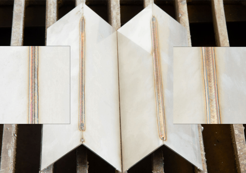
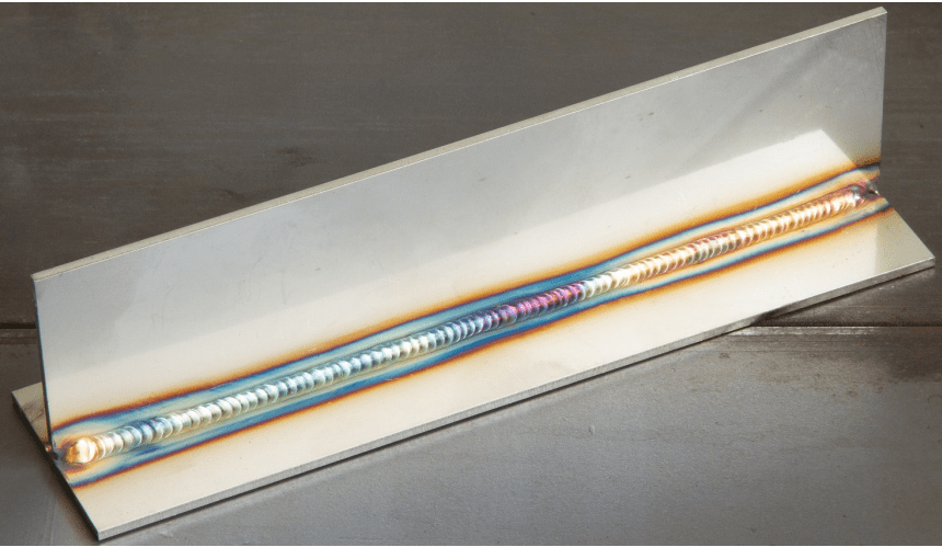
The image shows that, unlike double pulse TIG’s narrower arc, the wide arc generated by a low-speed pulse (on the left) lacks the ability to melt the corner at high travel speeds (450mm/min). The narrow and stable arc of the double pulse process on the right, performed well at this travel speed.
Numerous mechanised and manual welding tests of the new method were conducted. The results of the new process were compared with the results of the conventional pulse-TIG processes (low and high-speed pulse) and the quality and productivity improvements were considerable.
By combining the properties of two distinct pulse methods, the process also delivers the benefits of these two pulse types. Thanks to the high-speed pulse, the arc in double-pulse welding is narrow, well-focused, rigid and easy to target. In addition, the temporary high power generated by the low-speed pulse enhances the fluidity of the weld pool, enabling a higher travel speed with certain joint types (for fillet and overlap welds). The low-speed pulse’s temporary low power can be used in the solidification of the weld pool, which improves properties connected with position welding.
Benefits of Double-Pulse TIG Welding Process
The Kemppi double-pulse TIG welding process offers numerous benefits including:
- A narrow and stable arc, which is easy to direct to a corner
- Higher travel speeds than in a conventional TIG process
- Lower welding currents
- Greater tolerance of an inconsistent root gap when compared to a conventional TIG process
- Consistent travel speed
- Tack welds of consistent quality
- Improved suitability for position welding when compared to those offered by TIG processes
- The ability to achieve a fish-scale appearance without the need for a special welding process
- The option of producing differential penetration
Applications
As the double-pulse method brings together the benefits offered by low and high-speed pulses, it is suitable for a wide range of applications and in particular:
- Work involving thin sheets
- Fillet and corner welding
- Welds with strict requirements for visual quality
- Stainless steels
- Metals that require low heat input, such as high-strength, duplex and super austenitic steels
- Challenging non-ferrous metals handled with DC welding, such as titanium
The new welding process is easy to apply and typically does not require testing for the correct parameters or any practicing in advance.
For more information or a demonstration of the new Double-Pulse TIG welding process call Kemppi Australia on (02) 8785 2000 or email sales.au@kemppi.com
by Graham Fry
70 Years of Kemppi!
August 30, 2019 in Articles
Kemppi’s story of becoming one of the world’s most recognized companies within the welding industry is a journey that spans over three generations. It is a story about hard work and resiliency, having faith in your dreams and courage to realize them. In seven decades, Martti Kemppi’s vision has grown into a pioneering company that employs over 800 welding industry experts in 17 countries.
Kemppi has amazed the welding world time after time. It has succeeded in producing inventions and innovations that have become standard solutions for the whole industry.
Not only are Kemppi a force in the welding and fabrication industry but also a valued Australian Welding Institute sponsor. We wish them all the best for the next 70 years and beyond!
by Graham Fry
How your business can benefit from ISO 3834 Certification
July 23, 2019 in Articles
While certification to ISO 9001 provides documented evidence as to the quality of your business management systems, it does not demonstrate in any way the capability of your workforce or business to undertake special processes, such as pipe, or pressure vessel welding, to the levels required by an increasing number of customers operating in the world’s specialist markets.
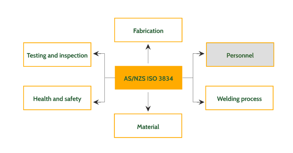
ISO 3834 part 1, the criteria required for quality requirements for fusion welding of metallic materials parts is laid out. This is recognised by the Australian Welding Institute (AWI) and international standards worldwide as the benchmark for a high-quality welding process.
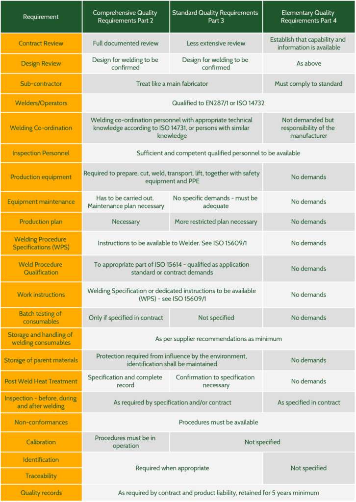
There are three levels of welding management 3834 part 2 – Comprehensive, 3 – Standard and 4 – Basic. The level the fabricator selects is based on the type of work they do and their clients’ requirements.
It should be of particular interest to companies involved in the welding of heat exchangers, pipelines and other pressure equipment, as well as those wishing to operate in the petrochemical industries, civil engineering, public infrastructure and defence sectors.
AS/NZS ISO3834 covers all aspects of the welding operation from pre-award technical review through to documentation and delivery conditions.
The benefits for certified fabricators
Although ISO 3834 can operate alongside 9001, it is not reliant on compliance with 9001.
Stand-alone, ISO 3834 compliance can provide a lot of positives for welding enterprises and their welding teams. Certification provides documented proof of your fabricator’s ability to produce high-quality products following a welding management system to the most stringent requirements.
It allows even the firms to be entered on the AWI register, hence boosting the chances of involvement in higher-value projects requiring ISO 3834 compliance.
Additional Benefits of ISO 3834 Certification
Although certification is not mandatory, it does provide a number of business benefits over companies that are not certified.
In a world where high-quality workmanship is paramount, maintaining certification provides for national and international companies to approach your business, safe in the knowledge you have the capability and credibility to undertake the required processes audited against a recognised standard in 3834.
All personnel involved in the certification process from the shop-floor to supervisors and higher management will benefit from increased process control, reducing rework and having defined clear instructions.
Certification provides the opportunity to expand your business operations, including sub-contract work for major international players such as the special process welding required in the petrochemical and civil engineering industries. Once the certification has been achieved, your business should operate more efficiently. You should notice reduced costs and overheads due to reduced production time and minimised reworks.
Technoweld can design and implement your ISO 3834 system to be certified by the Australian Welding Institute (AWI). The improved operational procedures and the high quality of completed products will increase customer satisfaction and likely lead to an increasing order book and higher profitability.
by Graham Fry
MasterTig – Far from the Ordinary
July 22, 2019 in Articles
60% Faster setup. 30% Increased welding speed. 20% Lower noise levels.

Overview
MasterTig sets new standards for weld quality, usability, and power efficiency in AC and DC TIG welding. Designed for professional welders, the MasterTig product family offers a choice of power variants up to 300 A. Its modular design philosophy allows you to build the specification that best meets your needs, including alternative control panels, wireless remote controls, and transport cart options.
Stylish, practical and robust, the MasterTig absorbs the knocks of everyday welding life. The compact-sized welding equipment is constructed from tough yet lightweight injection moulded plastic, featuring impact bridge protection structures. Flexible and durable Flexlite TX TIG torches are readily equipped to fit MasterTig to maximize welding comfort.
Benefits
- Choose from traditional touch button control panels or the full colour 7’’ TFT control panel, including Weld Assist and 99 memory channels per process
- Weld Assist guides every welder towards accurate, productive welding by recommending the best parameters for different welding applications
- Several useful features available for enhanced TIG welding
- Easy, fast and convenient coolant filling and cleaning
- MasterTig transport units feature floor level cylinder loading, removing the need for heavy lifting
- Compatible with Flexlite TX TIG torches
- Foot pedal, on-torch and hand remote controls available
- Option for connecting the equipment to WeldEye cloud service
Experience it
How does arc welding equipment look like when placed to your workshop or garage floor, or even in your living room? Experience the new master in the art of welding with augmented reality (AR) technology by downloading the Kemppi Discovery mobile application. Click here to know more.
by Graham Fry
The Latest in Steel Welding Technology
June 25, 2019 in Articles
Fronius is expanding its TPS/i welding system platform with the Steel Edition.
Fronius Perfect Welding is broadening its product range. The welding technology specialist is launching a new version of its current power source platform, called the TPS/i Steel Edition. The Steel Edition has been optimized for manual steel welding and impresses with an attractive price/performance ratio. Users benefit from different characteristics for standard and pulse welding. Additionally, the system has a WPS package containing welding procedure specifications that are certified in accordance with DIN EN 1090.
The TPS/i Steel Edition from Fronius is based on the current TPS/i power source platform. The welding systems have a modular design, can be adapted to individual requirements, and boast impressive networkability and comprehensive communication functions. Their powerful processors enable them to analyze and control welding processes with extreme precision. This ensures optimum results for a variety of welding tasks. The Steel Edition has been specially designed for manual steel welding. It has a variety of steel characteristics for both standard and pulsed arcs. Users are therefore able to carry out welding tasks on steel workpieces from a material thickness of one millimetre and above.
A highlight of the new Steel Edition is the PCS (Pulse Controlled Spray Arc) characteristic. This provides a particular advantage in the intermediate arc range. The smooth transition from a pulsed to a spray arc creates considerably less welding spatter. This, in turn, significantly reduces the amount of rework required. In addition, this characteristic features a focused arc that guarantees a deep penetration profile. It is particularly suited to small gaps, fillet welds, and root passes.
Welding Procedure Specifications for Standards-Compliant Work
The WPS package in the TPS/i Steel Edition contains welding procedure specifications for:
- Different steel grades
- Material thicknesses
- Filler metals
The WPS package eliminates the time-consuming and costly process of creating welding procedure specifications. This is particularly beneficial for companies that are required to comply with the European standard DIN EN 1090. Such companies are manufacturers of load-bearing steel constructions, using the specifications contained in the WPS package by the European standard.
The TPS/i Steel Edition is also equipped with the WeldCube Light data recording and analysis system. The system documents the process and proves that the weld seams have been created in accordance with the certified welding procedure specifications. The TPS/i records a wealth of information for each weld seam, such as:
- Time
- Duration
- Current
- Voltage
- Wire speed
- Power
This data is saved in the internal TPS/i data memory. Users can view the data using the TPS/i SmartManager and export it as a PDF. This makes it easy to document all weld seams. Users can upgrade to even more comprehensive data management functions at any time with WeldCube Basic or WeldCube Premium.
Various Power Categories and a Comprehensive Range of Accessories
The TPS/i Steel Edition is available in various power categories, ranging from 270 to 600 amperes. Numerous features ensure ease of use, such as a clear touch display that makes for simple and intuitive operation. The system can also be equipped with the Fronius JobMaster welding torch. The JobMaster welding torch displays the most important welding parameters on the handle of the welding torch. It allows the user to adjust the settings on the handle itself. In addition, user management with cards or key fobs allows individual authorizations to be created. This reduces errors caused by improper operation.
The Steel Edition can also be 02/2018 2/4 combined with the K4 fume extraction torch, which removes welding fumes at the point of origin. An optional dust filter makes it easier to use the welding system under harsh environmental conditions. The filter protects the system by preventing contaminants that hinder the function of the machine from entering the housing.
Business Unit Perfect Welding
Fronius Perfect Welding is the innovation leader for arc and resistance spot welding and is the global market leader for robot-assisted welding. As system providers, Fronius Welding Automation also turns customer-specific automated complete welding solutions into reality. This technology is used in a number of areas, from container construction right up to cladding for the offshore sector. Power sources for manual applications, welding accessories and a wide range of services add to our portfolio. With more than 1,000 sales partners worldwide, Fronius Perfect Welding is never far away from our customers.
by Graham Fry
Kemppi unveils the Gamma helmet range
June 24, 2019 in Articles
Kemppi unveils its Gamma helmet range to set a new global benchmark for welder protection, health and safety.
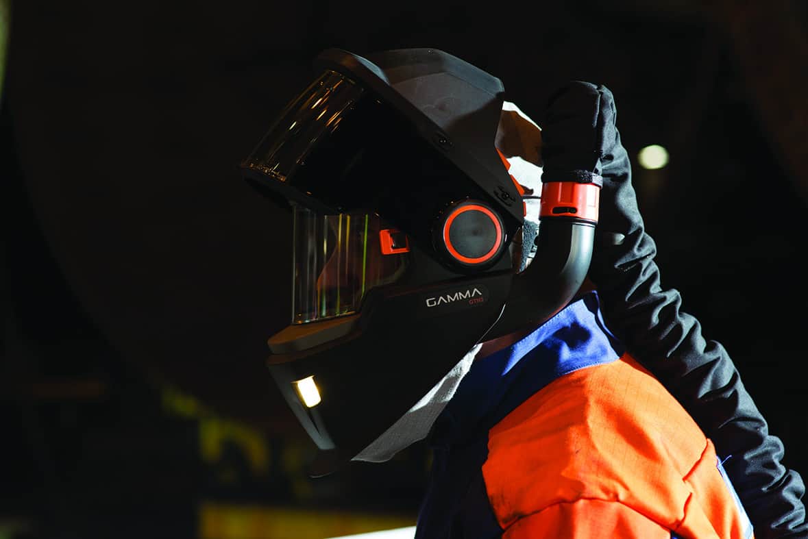
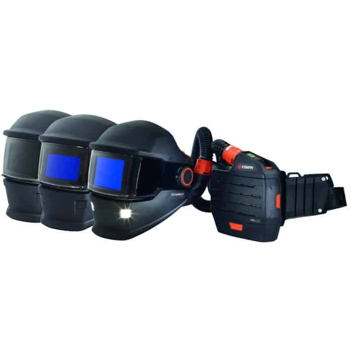
Leading international welding equipment manufacturer, Kemppi, has launched its new Gamma range of helmets for welders. The personal gear offers welders the best protection for the eyes, face and respiratory system. It also integrates work lights for clear vision and safety in low light working conditions. The Gamma range reduces work fatigue, increases comfort, and helps guard against welding related health hazards. Designed to deliver maximum protection and safety for welding professionals, the Gamma family now sets the global benchmark.
Increased respiratory safety for welders
Intense light and heat from the welding and cutting arcs are known hazards in welding workshops. However, welding also contaminates the surrounding air. Fumes from welding and cutting contain dangerous elements that are generally not visible to the naked eye. These fumes pollute the breathing air and can pose serious health risks.
Typically, welders can breathe 4,000 litres of air in an 8-hour work shift. If the lungs are unprotected, tiny fume particles can pass deep into the lung structure. This can cause serious health risks through long and short-term exposure to the contaminated air.
The new Gamma series protects welders from 99.8% of airborne fumes and particulates. ‘The Gamma series, when used together with the new powered filter unit, meets the highest European Total Inward Leakage (TIL) classification for respiratory performance, class TH3 as well as Australian and New Zealand standards,’ said David Green, Managing Director, Kemppi Australia. ‘This places the Gamma series in a category all of its own when it comes to delivering maximum overall protection for the welder.’
Air quality features
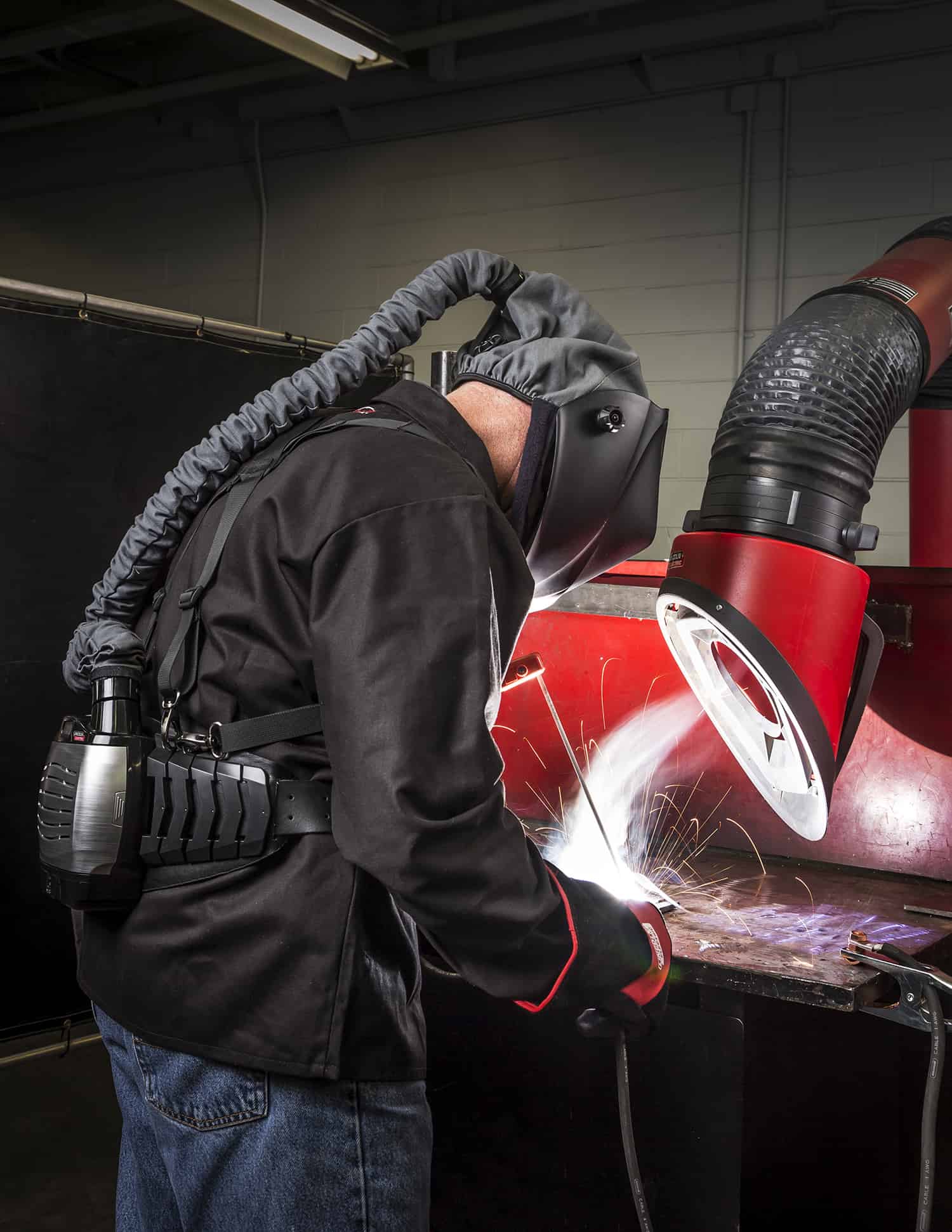
The Gamma GTH3 respirator models work on the ‘positive air pressure’ principal. It is powered from either a battery-powered filter pack or an airline breathing source. It excludes dangerous welding fumes and supplies clean and fresh breathing air into the breathing zone. These helmets ensure the welder enjoys a safe, cool and comfortable breathing environment when welding.
The PFU 210e filter pack is belt mounted and battery powered. It offers total freedom of movement around the work area while meeting the highest filtration performance for respiratory protection. Additionally, the supplied air models can be connected to a known breathing air system to meet the local breathing air standards.
The best welder helmet
Designed from the user’s perspective, the Gamma also provides excellent optical quality and large view areas. LiFE+ Colour auto-darkening welding filter technology enables greater clarity of vision. What’s more, when the welding visor is lifted, a 198 cm2 clear impact protection shield provides superb worksite views. These combined features improve work accuracy, increase safety, and reduce eye strain and work-based fatigue.
Plus, Gamma helmets with the auto-darkening welding filters are easy to adjust as they include the ‘Remote-RC’ feature. Remote control buttons are located on the inside, upper surface of the helmet shell. They allow welders to quickly and conveniently adjust the filter even when they are wearing the helmet.
Additional features
Other features that enhance the usability of the Gamma helmets include Axis regulation and GapView functions. They deliver fast and convenient adjustment of the viewing area for different working positions. For low light conditions, the XFA models integrate 70 lumen LED work lights to help improve visibility, comfort and safety.
To ensure maximum comfort, the ComFlex headband offers flexibility for the perfect fit to the welder’s individual head shape and preferences. The suspended weight of the helmet is distributed evenly to help reduce fatigue.
Welders can choose from a range of seven Gamma models. They include standard face and eye protection through to the advanced high-class respiratory solutions. The Kemppi range of welding helmets provides welders with a safe breathing environment throughout their working day.
The Gamma helmets are suitable for use in all arc-based processes including welding, cutting and gouging, and in grinding and inspection work.
For more information on the new Gamma family call Kemppi Australia on (02) 8785 2000 or email sales.au@kemppi.com
by Graham Fry
The importance of welding fume protection in the workplace
June 24, 2019 in Articles
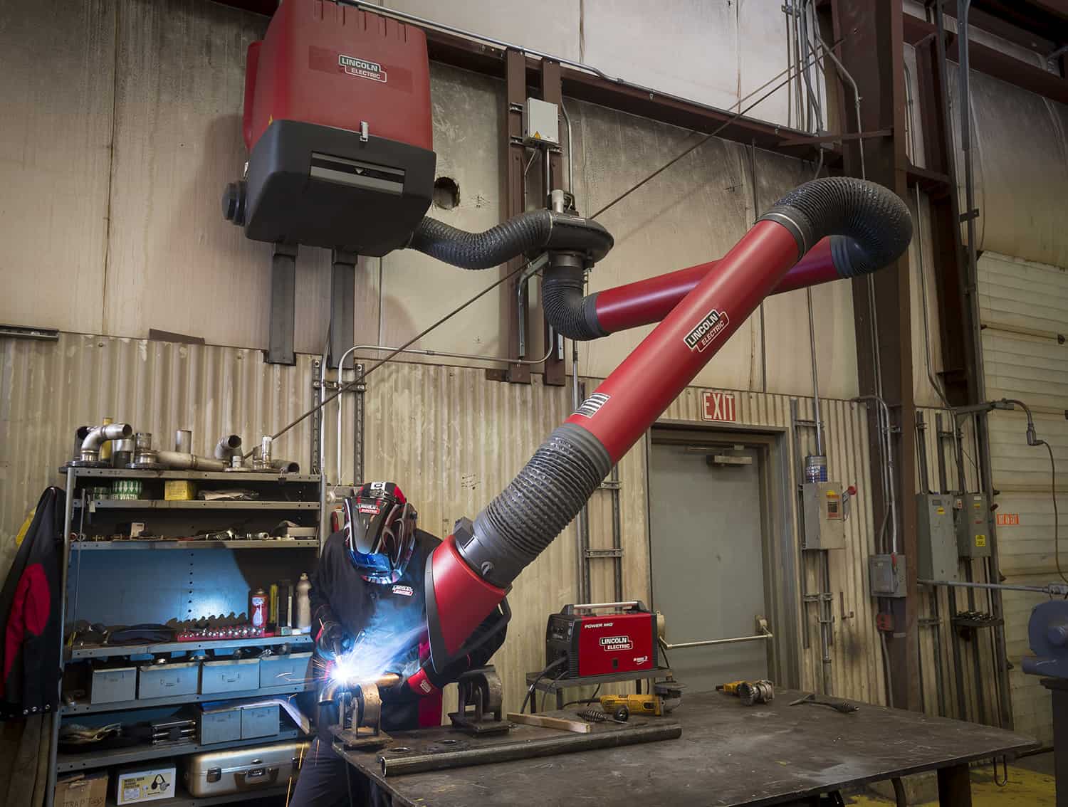
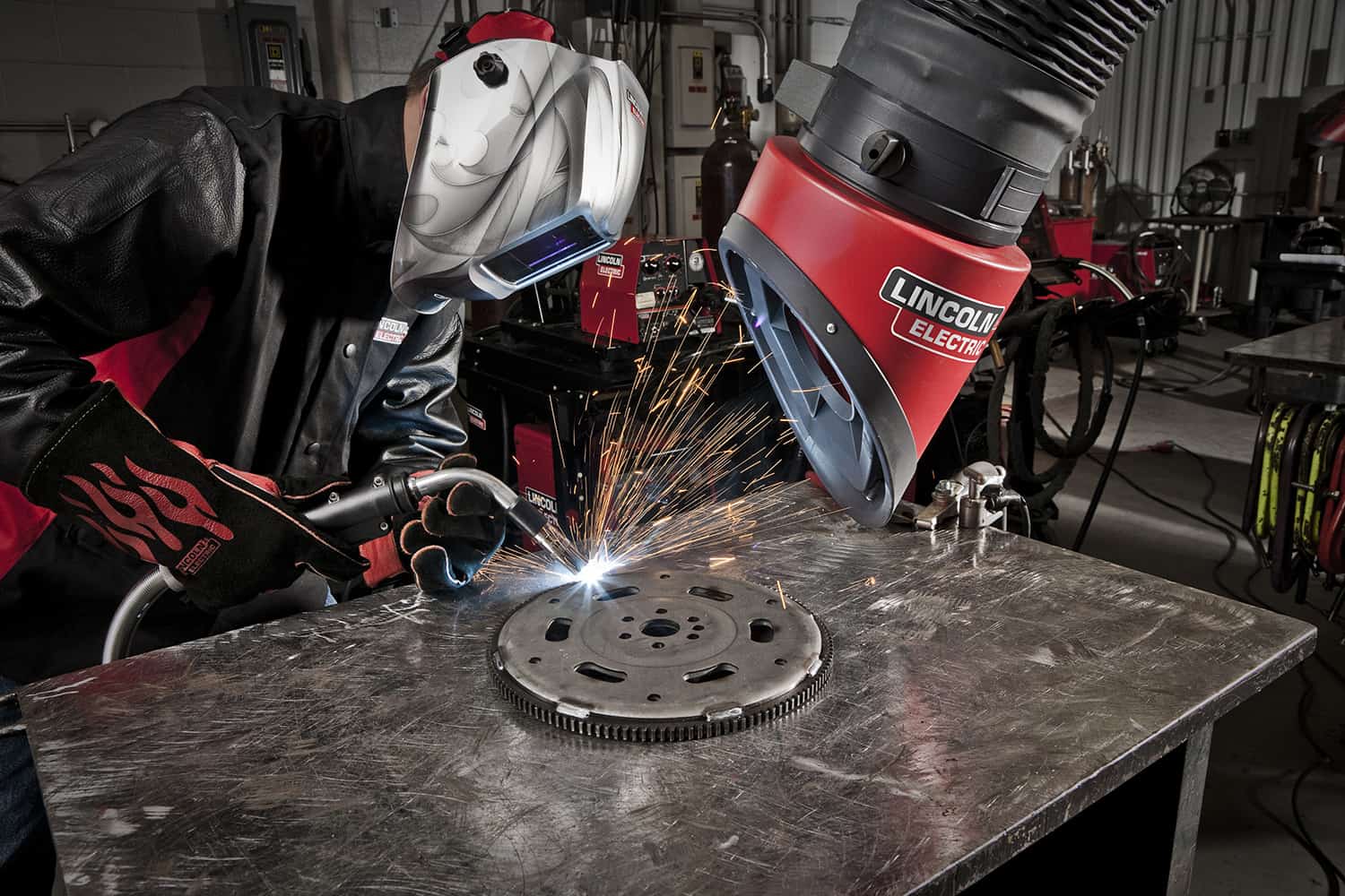
Lincoln Electric has served the welding industry by delivering industry-leading welding and cutting solutions since 1895. The company recognises the challenges faced by companies regarding productivity, quality and safety. They strive to respond to such challenges with innovative and dependable solutions.
How safe is your work environment?
Arc welding is a safe occupation when sufficient measures are taken to protect the welder from potential hazards. When these measures are overlooked or ignored, however, welders can encounter such dangers as:
- electric shock
- overexposure to fumes and gases
- arc radiation
- fire and explosion
Long-term and even short-term exposure may result in serious or even fatal injuries.
Ensure your safety
Lincoln Electric follows an in-depth process of evaluating the right weld fume control solution for applications. Their technical sales team is trained and knowledgeable about the exposure standards, the methodology of substitution, isolation, and ventilation. As a key partner, Lincoln Electric has a wealth of experience and knowledge of welding, welding fume and welding fume removal. This can aid customers in this process, more so than vendors with a focus only on air handling.
Plan to protect yourself and your staff
The Lincoln Electric weld fume control team understands and recognises that each welding application is unique with its own set of variables. As such, they know that there’s not one piece of equipment and consumable solution that fits every application. Likewise, every weld fume control application is unique. Their team will engineer a system to efficiently and effectively remove welding fume and particulate from metalworking operations.
Reach out for more information
Lincoln Electric’s weld fume control product portfolio includes a broad range of equipment for the capture, extraction and filtration of welding fume and particulate. As customers’ needs and regulations change, it will continuously evaluate and adjust and improve its product lines to meet those requirements.
Download our white paper on fume to read more.
by Graham Fry
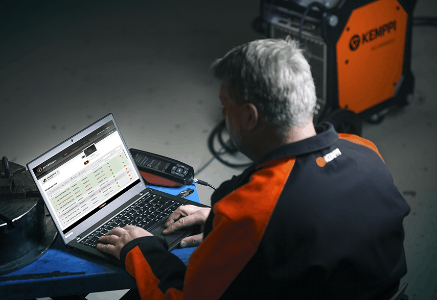
Kemppi ArcValidator – the only tool required for complete welding equipment validation
May 20, 2019 in Articles
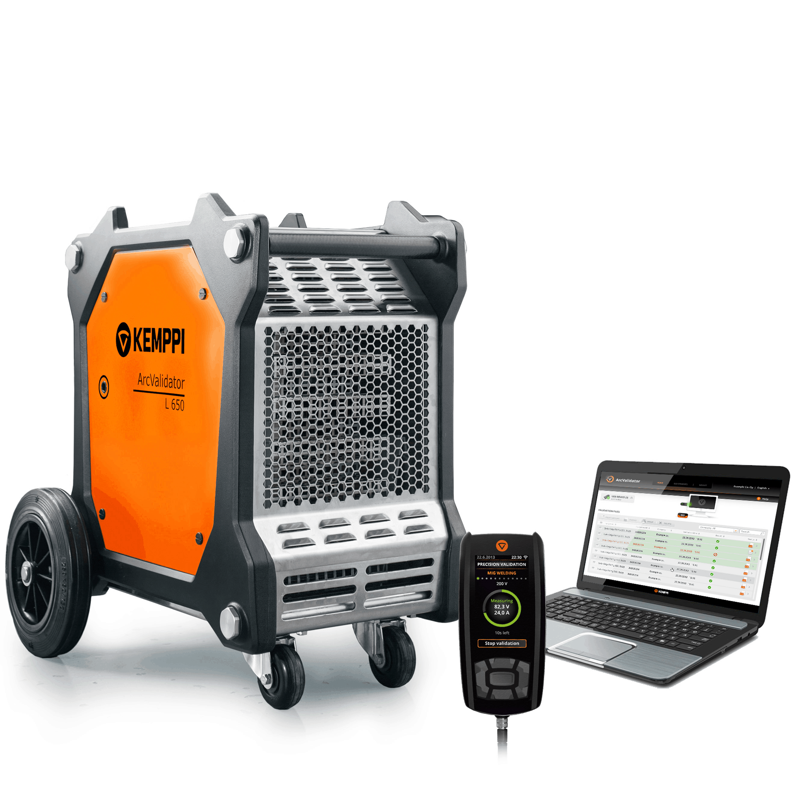
The Kemppi ArcValidator is a fully automated and universal solution for validating welding equipment. Fast, thorough and reliable, it removes the need for manual input and eliminates human error as part of the equipment validation process. Highly accurate, the Kemppi ArcValidator saves the user both time and money while providing detailed records.
The validation solution links both the workshop and office-based processes. The process meets both local quality control and national validation standards. This specifically includes Australian/New Zealand standards as well as ISO 3834 and EN 50504.
ArcValidator Solution
Applications
The ArcValidator is MIG/MAG, TIG and MMA compatible. It is used for current, voltage and wire feed speed validation of welding power sources and wire feeders.
The ArcValidator automates the validation process. It does not require manual adjustment of parameters or manual documentation of tolerances and it provides fast and effortless validation. All the tests and parameter adjustments are done automatically. This allows users to complete the process up to 80% faster when compared to manual validation. Not only does this help users save precious time but the process is also less prone to errors and delivers accurate results.
The solution also provides effortless reporting. PC software is included as standard with the ArcValidator. The software manages both the pre and post validation process and ensures accurate record keeping and standards-compliant documentation. The software also quickly creates pass certificates that can be printed and shared if necessary.
The ArcValidator PC software.
Features
The ArcValidator is equipped with an inbuilt wire feed speed measurement facility. The remote control is a smart, handheld device that fits in the palm of the user’s hand. It records all individual validation process data for later transfer to the PC software. The software guides the user throughout the validation process, using clear on-screen instructions.
Each validation has a unique reference number that lets users track assets. This is particularly valuable when working at large scale sites with welding machine fleets or at multiple small sites.
The ArcValidator is also equipped with an in-built wire feed speed measurement facility.
Benefits
The solution provides automatic, systematic and accurate validation for all of Kemppi’s sophisticated equipment including the FastMig M, FastMig X, KMS, Pulse and Kemparc Pulse.
The ArcValidator also makes the validation of other brands and multi-brand fleets possible as it is truly universal. It is compatible with all brands, models of welding machines and welding processes.
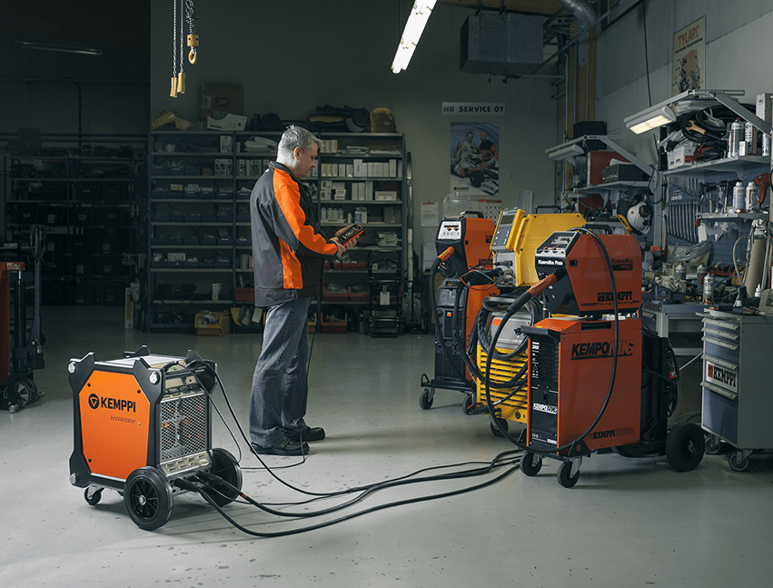
Easy to use, the ArcValidator is suitable for use in the following:
- Maintenance workshops
- Welding equipment service providers
- Hire companies
- Mobile service teams
- Educational institutions
The ArcValidator is also the perfect tool for anyone performing arc welding equipment validation services as a business. It offers a fast return on investment. For businesses validating welding equipment on a daily basis, ArcValidator’s capital investment costs can be recovered within the first year.
‘Regular calibration of welding power is often a standard requirement to meet internal company policy and welding quality management standards. The Kemppi ArcValidator automates this process to provide fast and accurate validation. It’s also suitable for use with any brand of welding equipment, making it an efficient and effective industry-wide solution,’ said David Green, Managing Director, Kemppi Australia.
Learn more about the Kemppi ArcValidator or email Kemppi for further enquiries.
by Graham Fry
Vision System for Monitoring and Control of Arc Welding
April 11, 2019 in Articles
Introduction
A shortage of skilled welders and a need for welds of a consistently high quality is fuelling an increasing demand for automated welding systems. As well as delivering consistency and quality, these systems have the added benefit of removing the operator from the hazardous welding environment, satisfying increasingly stringent health and safety regulations.
However, to be a viable alternative to manual welding, automated systems must be able to tolerate comparable part variations.
In mechanised applications, welding tends to be performed using pre-set welding parameters and so highly consistent and repeatable parts and alignment are required for high-quality results. Manufacturing tolerances of upstream operations, such as profile cutting and edge preparation, variation in the chemistry and accuracy of assembly, can all significantly affect the quality of the welding operation, yet can be challenging and expensive to control.
The weld pool characteristics provide important information about the weld quality. For example, there is a strong correlation between weld pool width and the degree of penetration in tungsten inert gas (GTAW) welding. The weld pool width, volume and position relative to the joint are also important in determining the surface profile of the weld and the likelihood of the presence of imperfections such as lack of fusion and penetration. High-quality images of the weld pool are essential to be able to detect weld pool deviations and to implement the necessary changes in the welding parameters or to track the joint in real-time, in order to maintain the weld quality.
Vision-based systems are employed industrially for remote monitoring of the arc welding processes in mechanised applications. The main difficulty encountered by operators is the high intensity of light emitted by the arc, which prevents good visibility of the weld pool.
The image quality that the operator obtains from vision-based monitoring systems is often not sufficient to allow judgement regarding the need for in-process parameter adjustments. As a consequence, vision-based systems are generally limited in their industrial use to a visual aid for joint tracking and qualitative monitoring of the process. With improvements to vision systems, they could be used for quality monitoring and in-process control.
Monitoring Techniques
The main difficulty in vision-based systems is to eliminate the high-intensity arc light, which prevents good visibility of the weld pool. The spectrum ranges from the ultraviolet at about 350nm through the visible region and into the infrared at about 850nm. A narrow band-pass filter can be placed in front of the camera to eliminate the arc light. This filter only allows light of limited wavelengths to pass through. The filter is chosen for a wavelength where the arc light intensity is low.
However, the band-pass filter darkens the image, making it difficult to see the weld. By adding an illumination source, an overall view of the welding area can be obtained. The wavelength of the emitted light must be in the same range as the band-pass filter. This can be achieved using a laser light source. Figure 1 shows the effect of the band pass filter with the laser light source. The result of this combination is a much-attenuated arc light with a dominant laser light which illuminates the weld pool and its surroundings.
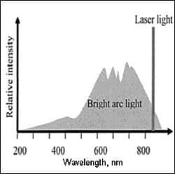
Fig. 1. Principle of spectral filtering
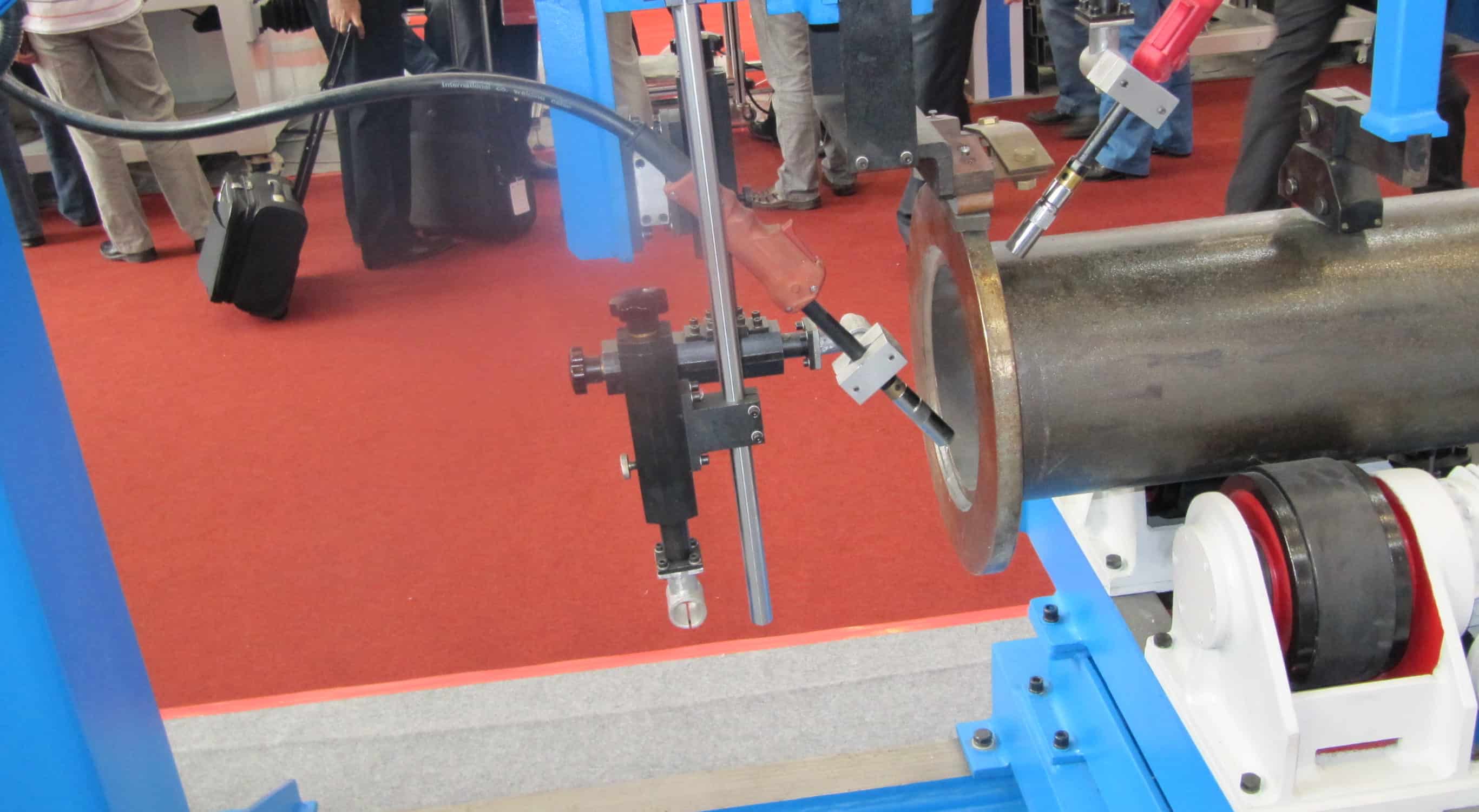
Using a laser to provide the illumination is expensive and not ideally suited for production applications due to health and safety requirements. So a system has been developed based on low-cost laser diode illumination. An illumination source of 16 laser diodes operating at a wavelength of 905nm has been demonstrated to be suitable for monitoring applications. The vision system is capable of producing good images of TIG and MAG welding (Figure 2), successfully eliminating most of the arc light from the image.
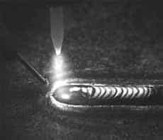
Fig 2. Image of TIG welding
Welding defect detection and adaptive control
The improved clarity of the weld pool images as a result of eliminating the arc is expected to be beneficial for real-time image processing applications in TIG welding. The weld pool edges are clearly defined, and it was also possible to see the joint line for tracking purposes.
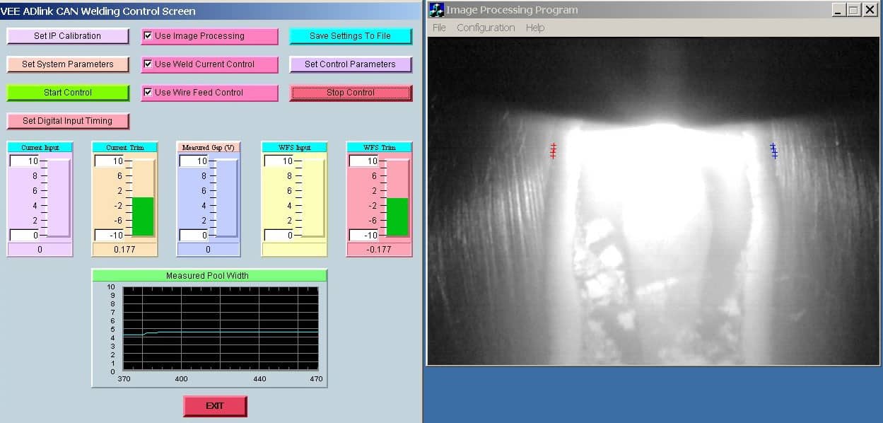
A good image of the weld pool width can be used in a feedback control system to automatically adjust the welding parameters to maintain weld pool geometry, for example when a component heats up or heat transfer is variable. An example of a control system developed in a European collaborative project is shown in Figure 3.

Fig 3. Screen display of a system for controlling bead width in TIG welding
Furthermore, with high-quality images, it may be possible to detect defects in the weld occurring in real-time either by observing the weld pool or the weld bead immediately after deposition.
Summary
Vision-based systems are employed industrially for remote monitoring of the arc welding processes in mechanised applications. The main difficulty encountered by operators is the high intensity of light emitted by the arc, which prevents good visibility of the weld pool. The image quality that the operator obtains from vision-based monitoring systems is often not sufficient to allow judgement regarding the need for in-process parameter adjustments.
By filtering out most of the arc radiation with a band-pass filter and illuminating the weld pool and surrounding area with light from laser diodes at the same wavelength, a good image of the weld pool is obtained. Alternatively, HDR cameras provide a good view of the weld pool without external illumination.
Vision systems can be used for real-time monitoring, adaptive control and defect detection in arc welding processes.
Copyright © TWI Ltd
The content of this article was correct at the time of publication.
This article was written by Geoff Melton