by Graham Fry
Welding Austenitic Stainless Steel – Part 1
July 1, 2014 in Job Knowledge
Welding of austenitic stainless steel – Part 1
There are a number of different types of steels that may be referred to as ‘stainless’; previous articles have considered ferritic and precipitation hardening steels for example. It is therefore advisable to be specific and to refer to the group to which the steel belongs in order to avoid confusion.
Although commonly referred to as ‘stainless steel’, the steels covered in this article should be more correctly referred to as austenitic, 18/8 or chromium-nickel stainless steels. As with the other types of stainless steels, the austenitic stainless steels are corrosion and oxidation resistant due to the presence of chromium that forms a self-healing protective film on the surface of the steel. They also have very good toughness at extremely low temperatures so are used extensively in cryogenic applications. They can be hardened and their strength increased by cold working but not by heat treatment.
They are the most easily weldable of the stainless steel family and can be welded by all welding processes, the main problems being avoidance of hot cracking and the preservation of corrosion resistance.
A convenient and commonly used shorthand identifying the individual alloy within the austenitic stainless steel group is the ASTM system. This uses a three digit number ‘3XX’, the ‘3’ identifying the steel as an austenitic stainless, and with additional letters to identify the composition and certain characteristics of the alloy eg type 304H, type 316L etc; this ASTM method will be used in this article.
Typical compositions of some of the alloys are given in Table 1. The type 304 grade may be regarded as the archetypal austenitic stainless steel from which the other grades are derived and changes in composition away from that of type 304 result in a change in the identification number and are highlighted in red.
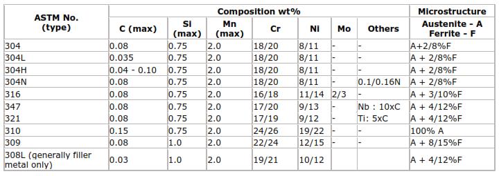
Table 1 Typical compositions of some austenitic stainless steel alloys
The 3XX may followed by a letter that gives more information about the specific alloy as shown in the Table. ‘L’ is for a low carbon austenitic stainless steel for use in an aggressive corrosive environment ; ‘H’ for a high carbon steel with improved high temperature strength for use in creep applications; ‘N’ for a nitrogen bearing steel where a higher tensile strength than a conventional steel is required.
These suffixes are used with most of the alloy designations eg type 316L, type 316LN, type 347H, where the composition has been modified from that of the base alloy.
Austenitic stainless steels are metallurgically simple alloys. They are either 100% austenite or austenite with a small amount of ferrite (see Table 1). This is not the ferrite to be found in carbon steel but a high temperature form known as delta (δ) -ferrite. Unlike carbon and low alloy steels the austenitic stainless steels undergo no phase changes as they cool from high temperatures. They cannot therefore be quench hardened to form martensite and their mechanical properties to a great extent are unaffected by welding. Cold (hydrogen induced) cracking (Job Knowledge No. 45) is therefore not a problem and preheat is not necessary irrespective of component thickness.
Alloying elements in an austenitic stainless steel can be divided into two groups; those that promote the formation of austenite and those that favour the formation of ferrite. The main austenite formers are nickel, carbon, manganese and nitrogen; the important ferrite formers are chromium, silicon, molybdenum and niobium. By varying the amounts of these elements, the steel can be made to be fully austenitic or can be designed to contain a small amount of ferrite; the importance of this will be discussed later.
In 1949 Anton Schaeffler published a constitutional or phase diagram that illustrates the effects of composition on the microstructure. In the diagram Schaeffler assigned a factor to the various elements, the factor reflecting the strength of the effect on the formation of ferrite or austenite; these factors can be seen in the diagram.
The elements are then combined into two groups to give chromium and nickel ‘equivalents’. These form the x and y axes of the diagram and, knowing the composition of an austenitic stainless steel, enables the proportions of the phases to be determined.
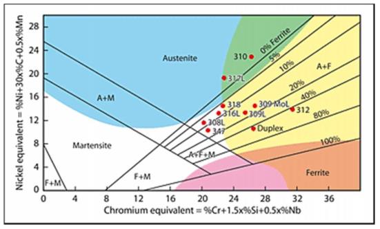
Fig 1. Shaeffler diagram (A-austenite; M – martensite; F – ferrite)
Typical positions of some of the commoner alloys are given in Fig.1. Also superimposed on this diagram are coloured areas identifying some of the fabrication problems that may be encountered with austenitic stainless steels.
Although all the austenitic stainless steels are sensitive to hot cracking (see the Job Knowledge article on Solidification Cracking), the fully austenitic steels falling within the vertically blue area in Fig.1 such as type 310 are particularly sensitive.
The main culprits are sulphur and phosphorus. To this end, these tramp elements have been progressively reduced such that steels with less than 0.010% sulphur and phosphorus less than 0.020% are now readily available. Ideally a type 310 or type 317 alloy should have sulphur and phosphorus levels below some 0.003%.
Cleanliness is also most important and thorough degreasing must be carried out immediately prior to welding.
The steels such as type 304, type 316, type 347 that fall within, or close to, the small uncoloured triangular region in the centre of the diagram contain a small amount of delta-ferrite and, whilst not being immune to hot cracking, have improved resistance to the formation of sulphur-containing liquid films. The reasons for this are that a) ferrite can dissolve more sulphur and phosphorus than austenite so they are retained in solution rather than being available to form liquid films along the grain boundaries and b) the presence of quite a small amount of ferrite increases the grain boundary area such that any liquid films must spread over a greater area and can no longer form a continuous liquid film. The 100% austenitic steels do not have this advantage.
One problem that has arisen with very low sulphur steels is a phenomenon known as ‘cast to cast variation’ or ‘variable penetration’. The weld pool in a low sulphur steel (<0.005%) tends to be wide with shallow penetration; a steel with sulphur over some 0.010% has a narrower, more deeply penetrating weld bead.
This is generally only a problem with the use of the fully automated TIG welding process, a manual welder being capable of coping with the variations in penetration due to the differences in sulphur content in different casts of steel. However, automated TIG welding procedures developed on a ‘high’ sulphur steel, when used to weld a low sulphur steel may result in lack of penetration type defects; the reverse situation may result in excessive penetration. Changes to the procedure that have mitigated, but never eliminated, this problem have included slow travel speed, pulsed current, use of Ar/H2 shield gas mixtures.
Other methods include specifying a minimum sulphur of, say, 0.010% or segregating the steels into batches with known penetration characteristics and developing welding procedures to suit. The A-TIG activated flux process has also been found to be of benefit.
The problems of welding the fully ferritic steels that fall into the pink area, where grain growth and embrittlement is a problem, have already been dealt with in Job Knowledge – Welding of ferritic/martensitic stainless steels.
The austenitic stainless steels falling into the yellow area will also embrittle but this is as a result of the formation of hard brittle phases called ‘sigma’ (σ) and ‘chi’ (χ). This embrittlement takes place in the temperature range of approximately 500 to 900°C. It is a sluggish process and is not a problem during welding of the austenitic stainless steels, but can occur in elevated temperature service or if the welded component is stress relieved.
by Graham Fry
Vernon Tool – Lincoln Electric
July 1, 2014 in Equipment
VERNON TOOL™ – A LINCOLN ELECTRIC COMPANY
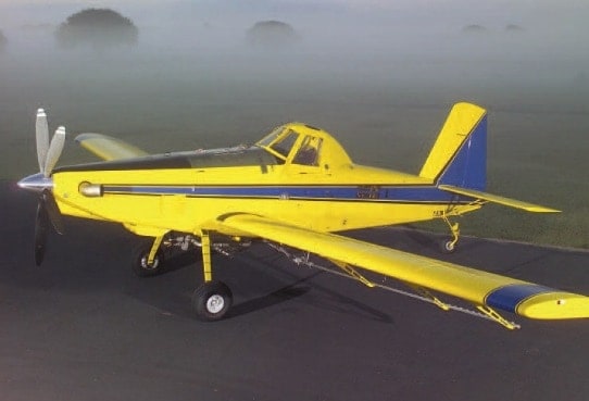
Air Tractor achieves high flying productivity with VERNON Tool™
Air Tractor, Inc. of Olney, Texas produces the world’s most extensive product line of aircraft for agricultural spraying, seeding, fertilizing or firefighting.
CHALLENGE
Improve the efficiency of manufacturing the over 120 tube sections that comprise a fuselage frame.
SOLUTION
MasterTube™ Cutting Machine (MTC) from VERNON Tool™, a Lincoln Electric Company.
RESULTS
- Fuselage frame tubes are cut and profiled in half the time.
- End profile is more accurate and requires less fine trimming.
On any day in Olney, Texas, you are bound to see a dusty cowboy walking through town or in sharp contrast; you will more than likely also see a brightly coloured, state-of-art firefighting plane soaring through the sky. Olney is a rural, relaxed town on the outskirts of Wichita Falls with a few surprises up its sleeve. The local landing strip seems to be a hotspot of activity for this unique, small town.
Recently renovated, this WWII-era airport has three long runways and serves as home to Air Tractor, Inc. A 100% employee owned company, Air Tractor is the world’s leading manufacturer of agricultural spraying and firefighting aircraft. Producing more than 2,400 aircraft since 1974, this motivated team of employees is quality driven and productivity conscious.
With more than 50 years associated with the design and manufacture of agricultural and aerial firefighting planes, the Air Tractor team continually proves they know their customers and they know their business. Being a global supplier and a results driven company, Air Tractor strives to improve productivity by repeatedly looking for new efficiencies in their manufacturing operation.
The Air Tractor plane design is an all tubular fuselage frame, with more than 120 different tube sections in each frame. Finding a method to produce tubes with profiled ends efficiently was a bottleneck the team needed to overcome. After several years of searching, the Air Tractor team determined that there were few affordable ways to profile small diameter tubes in an automated, effective manner.

MC09-104 11/09 © Lincoln Global, Inc. All Rights Reserved.
by Graham Fry
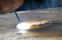
Manual Plasma Cutter
July 1, 2014 in Equipment
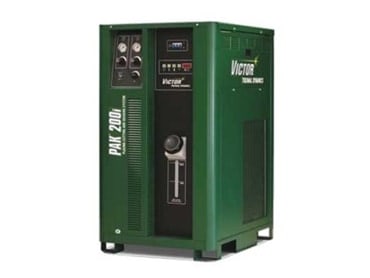
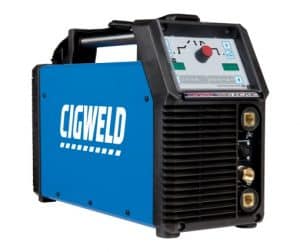
PAK 200i Manual Air-Plasma Cutting and Gouging System
CIGWELD Victor Technologies is excited to announce the introduction of the new PAK 200i Manual Air-Plasma Cutting & Gouging System.
Features of the new Pak 200i include:
- 200 Amps of Cutting Power
- Capable of hand cutting at 200 Amps with the ability to cut up to 70mm on mild steel. At full output will cut 254mm/min (10ipm) on 51mm mild steel.
- 100% Duty Cycle
- 100% duty cycle at full output
- Dual Gas Capability
- The dual gas system ensures superior quality and performance on ferrous and non-ferrous materials
- High Gouging Removal Rate
- Ability to remove up to 11.3kg of mild steel per hour
- Tip Saver for Optimal Tip Life
- This ensures that any accidental contact between the tip and work at high power levels will not damage the tip
The new PAK 200i has been intelligently designed to be used with the former PAK 200 Torches, Leads and Consumables.
With stock available in mid October, the PAK 200i is now available for ordering through your local CIGWELD Area Manager.
If you require any further information please contact your local CIGWELD Area Manager or call Customer Care on 1300 654 674.
by Graham Fry
News from SMENCO
July 1, 2014 in Articles
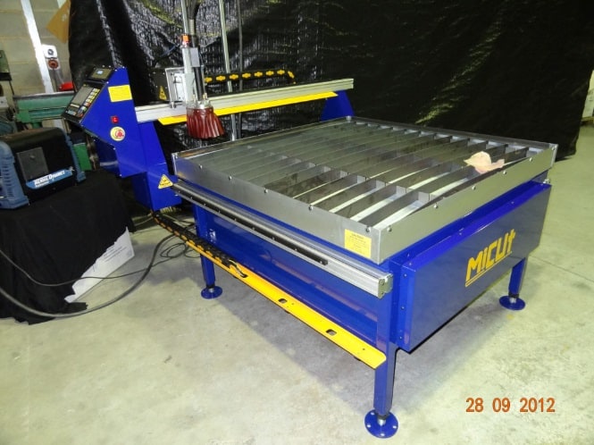
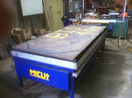
Made-in-Melbourne MiCut continues to lead CNC cutting industry
Since launching onto the local Australian market last year MiCut has gained a solid reputation in the industry for precision cutting ability, competitive pricing and a myriad of high-quality technical features.
Coupled with the added customer benefit of being able to talk directly with the developers and manufacturers of the machine, has made MiCut a welcome addition with CNC-cutting customers indicating they support the return of a home-grown product after years of foreign imports.
Australian distributor SMENCO, has also announced sharper pricing across the MiCut range to ensure they stay at the forefront of this competitive section of the industry.
Managing Director SMENCO, Anthony England: ‘ The MiCut is an all in one solution and our customers really appreciate that – no hassles about fume extraction or cable tracks or having to put it together yourself, it’s a one-stop shop approach.’
The Micut profile cutting machine range has unmatched accuracy and robustness in its class. All machines are designed and built in Melbourne with many parts sourced locally.
MiCut believes simplicity is the key to producing products that are easy to install, operate and maintain.
MiCut spokesperson, “We looked at existing CNC cutters on the market and came to the conclusion they were too complex and could be simplified.”
The result of that thinking is today’s MiCut which combines a simplified approach to CNC cutting with quality componentry. The end result is a cutting machine designed and built to deliver ongoing reliability, speed, accuracy and long life.

MiCut: The Facts:
MiCut 1212 – Cutting area 1230mm x 1230mm
MiCut 1224 – Cutting Area 1230mm x 2460mm
– 12×12 can be easily upgraded to 12×24.
– All Modules have plug in looms.
– Frame Constructed from powder coated Steel Heavy Box Section
– Small Machine Foot Print
– Speed Range – 75 to 6000 mm per min
– Hardened Linear Guides (X and Y Axis Z Axis)
– Rack and Pinion Drive – hardened and precision ground gears with precision rack
– All Sensors connected by IP67 plugs
– Heat shield
– Adjustable Front, Rear and Side Proximity sensing full travel limits
– MiCut “Quick Shield” – Remote lift and lower shield for increased protection
– Oxy Kit Available with Quick changeover
– Water Table – for dust and fume reduction
About MiCut
3 Tower Court
Noble Park Vic 3174
+ 61 3 9798 1012
About SMENCO
SMENCO is one of Australia’s leading distributors of welding equipment, consumables and associated welding technology from around the world.
Among other leading international brands, SMENCO is the national distributor for Fronius welding equipment and Castolin Eutectic – both recognised as leaders in Welding Technology and Wear Solutions, also Bohler Welding Consumables, Kemper Fume Extraction, Bug-O Automated Welding Systems as well as BOA Bore Repair Systems.
Based in Melbourne with offices in all states, SMENCO personnel have an enviable reputation for knowledge, experience and commitment to their customers and their industry.
SMENCO company trained and experienced field staff are backed by a comprehensive national Distributor Network to provide customers with service that’s never far away.
SMENCO Pty Ltd
I Longview Court
Thomastown
Victoria 3074
1300 728 422
by Graham Fry

Worldskills Australia
July 1, 2014 in Articles
WorldSkills is an international initiative that identifies and nurtures “Trade” and “Skill” talent around the globe. It’s about selecting the best up and coming young talent across a range of skills, and having them compete against one another in their chosen event. They first compete at a regional level, then at the national level, and in the final stage they are sent abroad to step up to the plate on a world scale, and represent their country at the International Competitions which are run every second year.
This year there were 44 Trade and Skill Categories being represented at WorldSkills in Australia.The Skills and Trades ranged from heavy industrial work like Welding or Construction Steel Work,to Plumbing, Auto Body Repair or Landscaping. At the other end of the spectrum, the competition also encompassed Skills such as jewellery, cookery, hairdressing and web design.
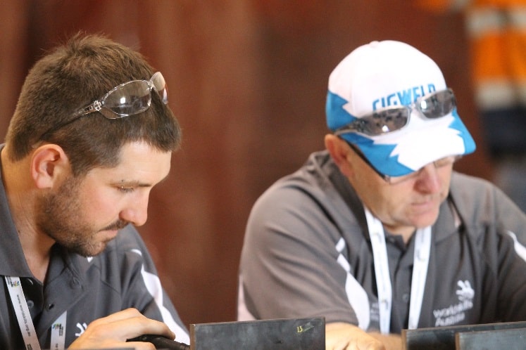
The WorldSkills 2014 National Competition was held in Perth – and ran officially from the 18th – 20th September. The day before the competition began, all of the competitors had an official welcome ceremony, and were brought into their respective skill stations where they were given a couple of hours to get accustomed to their workstations and equipment.
The competitors were given 8 hours a day, over 3 days, to complete a given task. Each competitor worked on their own to build, repair or create their project from scratch. To help them along, a number of high profile companies chipped in to provide all of the relevant equipment, utilities and consumables that were required to complete the set task.
CIGWELD is a major Sponsor of WorldSkills Australia, and have supported this years event with a generous range of Professional Level Welding Machines, Safety Equipment and Consumables. The range of CIGWELD equipment assisted competitors with the welding, cutting and gas control, which was required within a number of the Skills and Trades.
These categories included: Welding, Sheetmetal Work, Construction Steel Work, Auto Body Repair, Plumbing and Jewellery.
CIGWELDs Comet Edge Regulators featured heavily throughout the event, as the solution for all gas control.The Comet Edge Blow Pipe and Cutting Attachment, Transmig 175i, Transmig 250i and Professional 220ACDC Inverter are just a few of the CIGWELD products that you would have seen in the Skillaroos workstations.
For a smooth transition into the workforce, gearing competitors with Professional CIGWELD machines provided them with the confidence and knowledge required to enhance their skills to use industry level equipment.
With safety being paramount at CIGWELD, machines are equipped with the latest in welding safety technology – VRD, Voltage Reduction Device, virtually eliminating electric shocks when not welding.
CIGWELD was an initial founder of Worldskills in Australia some years ago, and will continue to support this important program which assists with the development and education of our younger up and coming welding professionals, enhancing both their skills and experience. CIGWELD does more than donate funds and equipment to Worldskills; as a Major Sponsor, staff are involved nationally, and when required, devote time to judging competitions.
CIGWELD Marketing Manager, Laura Carrazza, explains that the WorldSkills sponsorship is just as important to CIGWELD, as it is to the WorldSkills organisation and the Competitors. “The exposure we get from being involved with such an important competition is immeasurable, as it is really about establishing a relationship and loyalty with our young, talented future professionals. The main aim is to have presence at the events, and we believe that through our sponsorship we are able to establish significant brand awareness, and as a result be instrumental in the growth and development at a grass roots level.”
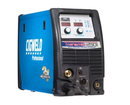
The Welding category was where the largest range of CIGWELD welding equipment was located. The contestants used CIGWELD Transmig 250i Multi Process Welding Inverters, along with 220ACDC Welding Inverters and a range of CIGWELD wires, electrodes and TIG rods. All contestants were decked out in CIGWELD safety gear (Gauntlet or TIG gloves and high impact ProLite Auto Darkening Welding Helmets).
TRANSMIG 250i:
The CIGWELD TRANSMIG 250i is a self contained single phase multiprocess welding inverter that is capable of performing GMAW/FCAW (MIG),MMAW (Stick) and GTAW (Lift TIG) welding processes. The unit is equipped with an integrated wire feed unit, voltage reduction device (VRD applicable in stick mode only), PFC (power factor correction), digital voltage and amperage meters, and a host of other features in order to fully satisfy the broad operating needs of the modern welding professional.
 TRANSTIG 220 AC/DC:
Great for the highest quality aluminium weld, the Transtig 220AC/DC combines the finest hardware with the latest digital software control systems, producing outstanding seam quality on even the thinnest materials. With DC stick, AC/DC Lift TIG and AC/DC HF TIG and jam packed with safety features, the Transtig 220 AC/DC is ideal for a range of industries, from boat building and panel beating to precision work in chemistry, wine or water tank installations. Whilst in TIG mode the Transtig 220AC/DC is capable of Pulse Welding, Spot Welding, 2T (Normal) and 4T (Latch) modes.

Welding competitors were asked to perform a number of welding tasks, demonstrating various welding positions, across a range of processes (MIG, TIG and Stick) and also on a range of metals (Mild Steel, Stainless Steel and Aluminium).
The main project was to construct a fully assembled pressure vessel that was visually assessed, as well as pressure tested by judges. Once a winner was selected, that individual then had the opportunity to take on the challenge at the International Worldskills competition in Brazil next year.
A world-class competition which has hundreds of millions of government and industry money poured into it, to make it the renowned event that it is today. We look forward to seeing our Skillaroo competitor’s progress to this next level, and are thrilled that CIGWELD has been a part of this gateway to success and instrumental in their careers.
Winners from CIGWELD Supported categories:-
METALS & ENGINEERING CATEGORIES
WELDING
GOLD – KALLON McVICAR, ILLAWARRA NSW (WOLLONGONG)
SILVER – NATHAN KELLY, MACQUARIE – NSW (ORANGE)
BRONZE – ELTON STEWART-MURRAY, TASMANIA – TAS
CONSTRUCTION STEEL WORK
GOLD – JED SPARKES, SOUTHERN QUEENSLAND – QLD
SILVER – SCOTT BROWN ILLAWARRA – NSW (WOLLONGONG)
BRONZE – MICHAEL JAMES, RIVERINA MURRAY, NSW
ENGINEERING EXCELLENCE TEAM CHALLENGE
GOLD – TODD FITZSIMMONS & BROCK GOODWIN, HUNTER NSW
SILVER – BRADLEY CLARKE & MATTHEW LUTTRELL, TASMANIA – TAS
BRONZE – SHARI HUNT & MATTHEW KING, SPENCER GULF – SA
SHEET METAL WORK
GOLD – THOMAS CRITTENDEN, HUNTER – NSW
SILVER – HARRISON DENFORD, SYDNEY- NSW
BRONZE – HAMISH CHAMLEY, TASMANIA – TAS
JEWELLERY
GOLD – JYOTHI FORMAN, MELBOURNE – VIC
SILVER – DOUGLAS ELY, SYDNEY WEST – NSW
BRONZE – SAMANTHA KELLY, ADELAIDE – SA
BUILDING & CONSTRUCTION CATEGORIES
PLUMBING
GOLD – DYLAN Di MARTINO, MELBOURNE – VIC
SILVER – SAM GLISSON, BALLARAT/WIMMERA – VIC
BRONZE – SAM GIFFORD, RIVERINA MURRAY – NSW
REFRIGERATION
GOLD – BEAU KUPRIS, SYDNEY WEST – NSW
SILVER – JORDAN WALLWORTH, MELBOURNE – VIC
BRONZE – MARK YOUNG, TASMANIA- TAS
AUTOMOTIVE SERVICES
AUTOBODY REPAIR
GOLD – TRENT YEO, MELBOURNE – VIC
SILVER – KARL DAVIES, BALLARAT/WIMMERA – VIC
BRONZE – BLAKE HOLDEN, SYDNEY – NSW
INTERNATIONAL EXPERT OF THE YEAR AWARD
PAUL CONDRAN – WELDING
For additional information or photographs, please contact:
Laura Carrazza
Marketing Communications Manager – Asia Pacific
CIGWELD – A Victor Technologies Company
T: 03 9474 7329
M: 0435 968 356
by Graham Fry
SMENCO – Latest Product Release
May 1, 2014 in Equipment
Top marks for new Kemper Smartmaster
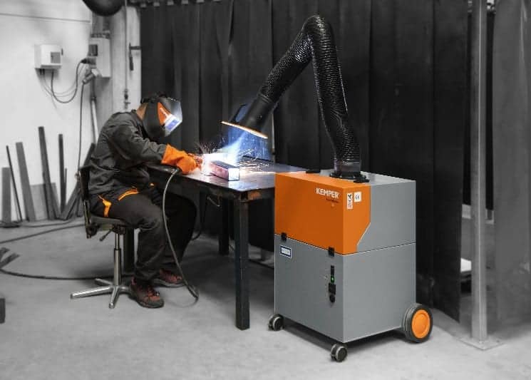
Kemper – the welding fume extraction and filtration experts – has released its new, compact and very affordable SmartMaster mobile fume extraction unit.
The SmartMaster mobile unit has been designed to offer all the features of larger fume extraction systems but in a compact, mobile, easy to use unit that is low priced so that even smaller companies can now afford fume extraction to protect their employees from dangerous welding fumes.
Kemper’s latest product release – distributed in Australia by SMENCO – will appeal to businesses that require a mobile welding fume extraction system for smaller work space areas with a quality filtration system at a low price.
The SmartMaster uses a three-stage disposable filter to remove dangerous potentially carcinogenic substances such as nickel oxides or chromium compounds at more than 99 per cent which are emitted during welding of stainless steel or other high-alloy metals. Due to its W3 approval the purified air can be recycled back into the work area.
A 360° rotatable arm, easily positioned exhaust hood and suction capacity of 950 m³/h at the exhaust hood, ensures that weld fumes are effortlessly removed from the work area. The SmartMaster can also be used for confined work areas by connecting a flexible hose from the back of the unit instead of using the exhaust arm. The unit even has an audible alarm to warn you when the filter requires replacement, further protecting the employee.
About Kemper
German based Kemper is the world market leader in extraction and filtration systems for the metalworking industry. Specialist areas include extraction and filter technology as well as storage and automation.
This also includes, among others, highly efficient filter systems which also filter ultra-fine dust particles from the air, extraction tables for cutting processes and a complete accessory line with regards to work safety and air pollution control for the metal-processing as well as the electrical and automotive industry.
About SMENCO
SMENCO is one of Australia’s leading distributors of welding equipment, consumables, and associated welding technology from around the world.
Among other leading international brands, SMENCO is the national distributor for Fronius welding equipment and Castolin Eutectic (both recognised as leaders in Welding Technology and Wear Solutions), Bohler Welding Consumables, Kemper Fume Extraction, Bug-O Automated Welding Systems, and BOA Bore Repair Systems.
Based in Melbourne with offices in Brisbane, Sydney, Perth and representatives in many regional centres, SMENCO personnel have an enviable reputation for knowledge, experience and commitment to their customers and their industries.
SMENCO Company trained and experienced field staff are backed by a comprehensive national Distributor Network to provide customers with service that’s never far away.
SMENCO Pty Ltd
I Longview Court
Thomastown Victoria 3074
1300 731 873
by Graham Fry

Welding Supervisors Exams
May 1, 2014 in Welding Supervisors
Welding Supervisors Exams have achieved great success
The recent examinations for certification as Welding Supervisor to either AS1796:2001 or AS2214:2004 have been held in venues in NSW and WA.
Papers A, B1 and B2 were available for candidates. Many took the opportunity to sit all three papers and gained themselves both Supervisor qualifications!!
The feedback from the candidates to AWI™ has been good and some of the comments are below:
“…..it wasn’t an easy exam but I appreciated the efforts you guys have gone to…”
“The facilities were great…well done to the AWI”
“…I like the idea of being able to sit all three exams if you wanted to, what a great idea”
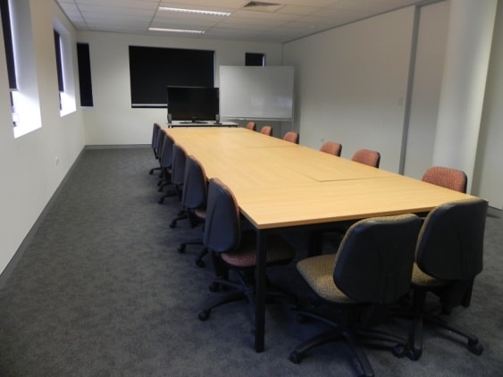
Photograph of some of the NSW exam candidates
As representatives of the Australian welding and fabrication industry, a key aim of the AWI™, is to provide a national welding qualification system for its members that is recognised by the industry’s key stakeholders and which extends across all states and territories.
The industry has been waiting for the return of a practical, relevant qualification, which is a cost competitive alternative to the offerings of the WTIA. Not only has the AWI™ been running AS1796:2001 Certification 1 to 9 for many months now, but as you are aware, this year, the AWI™ extended the program to include:
AS1796:2001 and AS2214:2004 certification for welding supervisors in the pressure vessel iindustry (certificate 10) and structural steel industry.
Certification 1 to 9 has seen a steady growth in the numbers of welding personnel again, wanting a cost competitive alternative to the offerings of the WTIA.
The AWI™ hope that the trend will follow on into the Welding Supervisors arena. The AWI™ are making this happen!
Examination papers have been written and validated by industry experts that have extensive experience in the relevant disciplines. The AWI™ is raising the bar on these important industry qualifications as well as giving you a quality alternative.
 AWI™ encourages its 600+ members and the Australian Welding and Fabrication Industry to embrace these qualifications. We have established an alliance with a number of TAFE Colleges nationally and take pleasure in supporting and promoting their programs.
The details of teh next rounds of exams follow on the next page. Application forms are available through selected TAFE Colleges or from: admin@welding.org.au
AWI™ Welding Supervision qualifications
Given the initial success of our offering of exams to date, the AWI™ is rolling out the next few round of examinations for certification for Welding Supervisors for
- AS1796 – Certificate 10 and
- AS2214 – Welding Supervisors – Structural Steel Welding.
Feedback from running the initial round of examinations support that we are on track:
‘they are based much more on what we need to know in the workshop’ and
‘it was a very detailed exam but based on practical application of being a supervisor’.
The AWITM has listened to key stakeholders – Industry, but more importantly -YOU – and have provided a  certification system that measures the skills and knowledge of welding supervisors. For example, there will not be questions on MIAB or Laser welding in the exam. Instead, we have elected to use the examination period to focus on the more ‘relevant skills’.
Examinations will be held in capital cities around the country based on demand on the following dates
- September 26th and 27th
- November 28th and 29th
To apply for these examinations contact your local AWITM contact or email admin@welding.org.au
The appropriate forms will be forwarded so you can complete them ready for the exams.
For those that have an existing welding supervision qualification through TAFE, another RTO’s or the WT IA we are offering you the opportunity to convert your qualifications into the AWI™ qualification. by sitting the examination at 50% cost.
It is easy to do, if you have evidence of the qualification, satisfy the requirements of AWITM and are willing to sit the exam all you do is apply to the AWI™ and sit the exam/s.
So if you would like to take this opportunity and prove to the industry your worth as a Welding Supervisor, here is your chance.
For more information, email: admin@welding.org.au
Watch this space for the roll out of Welding inspection qualifications.
by Graham Fry
NanoSteel and EndoTec
May 1, 2014 in Articles
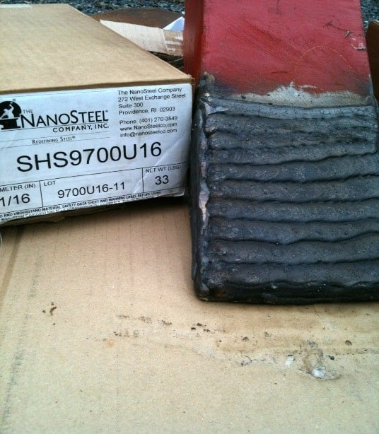
NanoSteel and EndoTec cored-hard facing wire does more with less
NanoSteel’s Super Hard Steel (SHS) and EndoTec cored wires for weld overlay applications are patented steel alloys which provide superior wear performance in extreme service environments for increasing the life of industrial parts and components.
When welded, NanoSteel SHS and EndoTec cored wires form a near nano-scale microstructure with a unique combination of high hardness and toughness properties.
This results in a uniform hard matrix with maximum hardness and wear resistance consistent throughout the entire SHS material layer.
SHS achieves maximum performance in one layer, requiring less material to exceed conventional alloy performance and resulting in a better price/ performance ratio.
Application processes: Gas Metal ARC Welding (GMAW), Open Arc Welding (OAW). Alternatives to chrome & complex carbides, tungsten and carbide alloys for wear.
About NanoSteel
NanoSteel is the world leader in proprietary nano-structured steel material designs.
NanoSteel has created generations of iron-based alloys from surface coatings to foils to sheet steel and powder metals. For the oil & gas, mining and power industries, NanoSteel has introduced commercial applications of metallic coatings to prolong service life in the most extreme industrial environments.
The company has formed a close relationship with Castolin Eutectic to support customers throughout the world. NanoSteel is distributed, sold and supported in Australia by SMENCO.
About SMENCO
SMENCO is one of Australia’s leading distributors of welding equipment, consumables, and associated welding technology from around the world. Among other leading international brands, SMENCO is the national distributor for Fronius welding equipment and Castolin Eutectic (both recognised as leaders in Welding Technology and Wear Solutions), Bohler Welding Consumables, Kemper Fume Extraction, Bug-O Automated Welding Systems, and BOA Bore Repair Systems.
Based in Melbourne with offices in Brisbane, Sydney & Perth plus representatives in many regional centres, SMENCO personnel have an enviable reputation for knowledge, experience and commitment to their customers and their industries.
SMENCO company trained and experienced field staff are backed by a comprehensive national Distributor Network to provide customers with service that’s never far away.
SMENCO Pty Ltd
I Longview Court
Thomastown Victoria 3074
1300 731 873 www.smenco.com.au
by Graham Fry
Welding Costs – Part 3
May 1, 2014 in Job Knowledge
Flux cored arc welding
The previous two articles dealt with the mechanics of costing a weld: how to calculate the weld volume and how to calculate the amount of welding consumables required to fill a weld preparation.
The final step in costing a weld is to determine the length of time to deposit this weight of weld metal. This is obviously a function of the deposition rate of the process.
The deposition rate is generally expressed as kgs/hr or lbs/hr deposited at a given welding current, welding continuously and without any breaks for electrode changing or deslagging.
The deposition rate will be affected by many factors and it will not be possible within the limitations of these articles to list the precise deposition rates for any specific process or welding current. Such data can be found in publications referenced below or by a web search. The ranges of approximate deposition rates for the commoner arc welding processes are listed in Table 1.
| Welding Process | Deposition Rate kgs/hr | |
| min | max | |
| MMA | 0.4 | 5.5 |
| MAG | 0.6 | 12 |
| FCAW | 1.0 | 15 |
| Single wire SAW | 3 | 16 |
Table 1 Indicative deposition rates – arc welding processes
To obtain an accurate figure for the specific parameters to be used is a relatively simple exercise. Weighing a plate, depositing weld metal using the required parameters on this plate for a fixed time and then re-weighing the plate will give an accurate figure that may be used for estimating purposes.
There is one golden rule for minimising the cost of making a weld and, whilst this may seem to be self-evident, it is worth repeating: deposit the minimum amount of the highest quality weld metal with the largest gauge electrode or wire at the highest current in the shortest possible time. This is obviously the ideal and can seldom be achieved in practice because of limitations on heat input, access etc.
The implications of applying the golden rule are:
- To deposit the minimum amount of weld metal the designer, aided by the welding engineer, must select the smallest weld preparation that is capable of providing the required weld quality. If the included angle is too narrow then lack of side wall fusion is a possibility with the consequent costs of repair; too wide an angle is wasteful in terms of deposited weld metal. Remember, though, that the cost of providing a weld preparation (by flame-cutting, edge planning, milling etc) must also be included in any costing exercise as must the cost of assembly. Machined weld preparations are more accurate than flame cut edges and this may result in faster set-up times and a reduced weld repair rate. It may be possible to use a square edge preparation by using the deep penetration characteristics of some of the welding processes; electron beam and laser welding are the best examples of this technique. Plasma-TIG and activated flux TIG can penetrate up to 10mm in a single pass; the ‘finger’ penetration of spray transfer MAG welding can penetrate up to 6mm and a submerged arc weld can penetrate up to 15mm. There is also the benefit when using a square edge preparation in that the consumption of filler metal is substantially reduced, the bulk of the weld metal being provided by the parent material. The final option on reducing costs when butt welding is for the designer to specify a partial penetration joint. The most expensive weld pass in any full penetration butt weld is the root pass and if this can be eliminated by using partial penetration joints then substantial savings can be made. However, the decision to use partial penetration welds should not be taken lightly but only if service conditions permit the presence of a large crevice at the weld root.
The designer will therefore need to consider whether fatigue, creep, corrosion etc are likely to occur and must clearly specify where the joints are permitted and the minimum acceptable weld throat.
- Depositing the highest quality weld metal infers that the weld repair rate will be reduced. Repair weld metal is very costly, particularly if the unacceptable defects are detected late in the fabrication programme; perhaps after final assembly where access is difficult or after post weld heat treatment. Accurate weld preparations and fit-up, easy access for the welder, welds made in the flat position and well trained welders will all help to minimise the weld repair rate.
- Depositing weld metal with the largest electrode or wire at the highest current will obviously give the highest weld deposition rate and shortest joint completion time. The deposition rate figures in Table 1give the minimum and maximum deposition rates at minimum and maximum welding currents. As an example, a 1.2mm diameter MAG wire at 120amps will deposit around 1.2 kgs/hr, at 380amps around 8 kgs/hr. To enable high welding currents to be used the item must be placed in the flat position and there must be easy access for the welder. One benefit of using the high welding currents is that the number of weld runs to fill the joint will be reduced and this, in most circumstances, will result in less distortion than a large number of low current weld passes. Remedial work to correct distortion can therefore be reduced. A further benefit when welding the ferritic steels is that high current and therefore high heat input may allow any preheat to be reduced or eliminated entirely.
However, there are limitations to this approach to improving productivity. If achieving high toughness is a factor then it is likely that heat input will need to be controlled when welding the ferritic steels, placing a limit on the welding current and travel.
speed. High welding currents also imply a large, fluid weld pool and it may not be possible to control this pool when welding in any other than the flat position – for example, MAG welding cannot be performed using spray transfer (high welding current) in the vertical position due to the absence.
of a flux to hold the pool in place. Using a manual process at such high currents also results in increased welder fatigue resulting in a reduced duty cycle. A solution to this problem is to mechanise or automate the process.
To achieve the most cost effective solution to producing a welded structure is therefore not simply to increase duty cycle or deposition rate but to consider all aspects of fabrication from the design stage to final inspection, involving all members of the team from designer to welder.
This article was written by Gene Mathers.
References:
Procedure Handbook of Arc Welding, Publication – Lincoln Co.
Standard Data for Arc Welding, Publication – TWI (out of print)
Welding Handbook Vol 2 Welding Processes, Publication – American Welding Society
Copyright © TWI Ltd 2014
The content of this article was correct at the time of publication. For more information visit: www.twi-global.com
by Graham Fry

Welding Costs – Part 2
May 1, 2014 in Job Knowledge
Part 1 of this article, dealt with the methods of determining the weight of deposited weld metal in a joint, enabling the cost of welding consumables to be calculated.
This is obviously the first step towards calculating the cost of actually making a welded joint but there are many other factors that need to be considered but which are beyond the scope of these articles.
The most significant of these costs is the overhead; the cost of providing a welding workshop or site and the costs of managing and running the organisation.
These costs are dependent on the accounting practices of the organisation. They comprise factors such as rent, rates, bank interest, cost of indirect workers, i.e. those not directly involved in fabricating, depreciation of plant etc.
In addition, other accounting decisions (for example, where the costs of machining and assembly are absorbed) may affect the decisions on which is the most cost-effective joining method.
One of the most significant costs is that of labour and this inevitably varies with industry, time and country. The costs mentioned above cannot generally be influenced by the decisions made by a welding engineer. These articles will therefore concentrate on those aspects of welding activities that are not subject to accounting practices, overhead or labour costs.
There are many costs, other than the cost of depositing weld metal that will affect the price of a welded fabrication.
The work done by the designer in designing the most cost-effective joint in an item that can be placed in the most advantageous position for welding will have major effect on costs. For example, the type of joint preparation the designer selects; a single or double-V preparation can be flame cut, a J-preparation must be machined and is generally far more expensive. A machined J-preparation, however, may have less volume than a single-V, depending on thickness; will be more accurate and therefore quicker to assemble within tolerance and may result in a lower repair rate leading to a lower cost than the V preparation.
Costs that are directly affected by welding engineering decisions, in addition to the cost of actually depositing weld metal, are therefore; joint preparation, assembly time (which includes positioning in any jig or fixture and tacking), cleaning and dressing the weld, removal from jigs or fixture, post weld heat treatment, costs of non-destructive testing and cost of repairs. The amount of weld metal deposited is rarely the same as the amount of filler metal purchased. This is the result of losses when, for example, GMAW or submerged arc welding wire is trimmed back to the contact tip, when the wire reel runs out and the length of wire between the drive roll and the contact tip is scrapped or the wire or reel is damaged.
Such losses tend to be quite small but this is not the case with coated electrodes. Damaged flux coatings, incorrectly stored electrodes and the stub ends discarded by the welder all contribute to as much as a third of the purchased weight of manual metallic arc electrodes being scrapped. Some electrode manufacturers’ catalogues give figures for these losses which can vary depending on electrode type and diameter.
To assist in calculating the amount of welding consumables to be purchased Table 1 gives some multiplication factors for the more common arc welding processes. The weight of weld metal in the joint should be multiplied by this factor to give the amount of welding consumable required. These figures assume good housekeeping and shop floor discipline such that consumables are not wasted or scrapped unnecessarily.
| Arc welding process | Multiplication factor |
| MMA (SMAW) | 1.5 |
| TIG (GTAW) | 1.1 |
| MIG/MAG (GMAW) | 1.05 |
| Sub Arc (SAW) | 1.02 |
| FCAW | 1.2 |
| MCAW | 1.1 |
Table 1 Multiplication factor. Weight of weld metal to give the weight of filler metal required.
The other consumables in this cost equation are shielding gases or flux.
The conventional shoulder height welding gas cylinder contains approximately 10,000 litres of shielding gas at a pressure of 200bar. As the gas flow rates normally used in production are around 12 to 15 litres per minute, this typical cylinder should provide in the region of 10 to 12 hours of welding time, allowing for losses at the beginning and end of the arcing period.
The rate of flux consumption in submerged arc welding is approximately 1kg of flux for every 1kg of deposited weld metal.
This assumes good housekeeping and an efficient flux recirculation system. Calculation of the amount required (and hence the cost) of these consumables is therefore relatively straightforward.
The cost of the welder’s time to weld a joint does not depend solely on the deposition rate of the process. A most important factor in determining the time required by the welder is what is known as the ‘duty cycle’ or ‘operating factor’. This is a percentage figure giving the amount of time that the arc is burning and weld metal is being deposited versus the total time that the welder is working. Table 2 gives some figures for the more common arc welding processes. Note that these do NOT include set-up or assembly time and individual circumstances can increase or decrease these figures.
| Arc welding process | Duty cycle % |
| MMA (SMAW) | 15 – 30 |
| TIG (GTAW) | 25 – 40 |
| Mechanised TIG | 80 – 90 |
| MIG/MAG (GMAW) | 30 – 45 |
| Mechanised MIG/MAG | 80 – 90 |
| Sub Arc (SAW) | 80 – 95 |
| FCAW | 25 – 45 |
| Mechanised FCAW | 70 – 85 |
| MCAW | 30 – 45 |
Table 2 Duty cycles for arc welding processes
The lost time in this figure can be accounted for by considering all of the other activities that the welder performs. In MMA welding, for example, time is required for tacking, de-slagging and cleaning a weld pass, for changing electrodes, for changing position, for rest breaks and for removal of the item from a fixture. Similar activities need to be performed using the other welding processes.
Increasing the duty cycle is therefore one method of increasing productivity, either by organising the shop floor such that lost time is reduced or by the use of a higher duty cycle process. However, remember that the arcing time may well be only a very small proportion of the total time to manufacture and attention to other aspects of the manufacturing cycle may give better returns than simply increasing the welding duty cycle. Reference to Table 2 also suggests that mechanisation is one method to increase the duty cycle. Caution needs to be exercised, however, if the total (floor to floor) time is to be reduced. For one-off or small batch items the time taken to prepare and set up a mechanised system to weld the item may be longer than that taken to weld using a manual process. Note also that if a mechanised system is used, the duty cycle may in fact decrease, as the welding speed is increased and the weld is completed in a shorter time although the number of items welded per day will increase. It is therefore essential to consider the complete manufacturing cycle to achieve the most cost effective solution.
by Graham Fry
Welding Costs – Part 1
May 1, 2014 in Job Knowledge
A previous article from the TWI (number 95), dealt with the methods of determining the weight of deposited weld metal in a joint, enabling the cost of welding consumables to be calculated.
This is obviously the first step towards calculating the cost of actually making a welded joint but there are many other factors that need to be considered but which are beyond the scope of these articles.
The most significant of these costs is the overhead; the cost of providing a welding workshop or site and the costs of managing and running the organisation.
These costs are dependent on the accounting practices of the organisation. They comprise factors such as rent, rates, bank interest, cost of indirect workers, i.e.those not directly involved in fabricating, depreciation of plant etc. In addition, other accounting decisions (for example, where the costs of machining and assembly are absorbed) may affect the decisions on which is the most cost-effective joining method.
One of the most significant costs is that of labour and this inevitably varies with industry, time and country. The costs mentioned above cannot generally be influenced by the decisions made by a welding engineer. These articles will therefore concentrate on those aspects of welding activities that are not subject to accounting practices, overhead or labour costs.
There are many costs, other than the cost of depositing weld metal that will affect the price of a welded fabrication.
The work done by the designer in designing the most cost-effective joint in an item that can be placed in the most advantageous position for welding will have major effect on costs.
For example, the type of joint preparation the designer selects; a single or double-V preparation can be flame cut.
A J-preparation must be machined and is generally far more expensive. A machined J-preparation, however, may have less volume than a single-V, depending on thickness; will be more accurate and therefore quicker to assemble within tolerance and may result in a lower repair rate leading to a lower cost than the V preparation.
Costs that are directly affected by welding engineering decisions, in addition to the cost of actually depositing weld metal, are therefore; joint preparation, assembly time (which includes positioning in any jig or fixture and tacking), cleaning and dressing the weld, removal from jigs or fixture, post weld heat treatment, costs of non-destructive testing and cost of repairs.
The amount of weld metal deposited is rarely the same as the amount of filler metal purchased.
This is the result of losses when, for example, GMAW or submerged arc welding wire is trimmed back to the contact tip, when the wire reel runs out and the length of wire between the drive roll and the contact tip is scrapped or the wire or reel is damaged.
Such losses tend to be quite small but this is not the case with coated electrodes. Damaged flux coatings, incorrectly stored electrodes and the stub ends discarded by the welder all contribute to as much as a third of the purchased weight of manual metallic arc electrodes being scrapped.
Some electrode manufacturers’ catalogues give figures for these losses which can vary depending on electrode type and diameter.
To assist in calculating the amount of welding consumables to be purchased. Table 1 gives some multiplication factors for the more common arc welding processes.
The weight of weld metal in the joint should be multiplied by this factor to give the amount of welding consumable required. These figures assume good housekeeping and shop floor discipline such that consumables are not wasted or scrapped unnecessarily.
| Arc welding process | Multiplication factor |
| MMA (SMAW) | 1.5 |
| TIG (GTAW) | 1.1 |
| MIG/MAG (GMAW) | 1.05 |
| Sub Arc (SAW) | 1.02 |
| FCAW | 1.2 |
| MCAW | 1.1 |
Table 1 Multiplication factor. Weight of weld metal to give the weight of filler metal required
The other consumables in this cost equation are shielding gases or flux.
The conventional shoulder height welding gas cylinder contains approximately 10,000 litres of shielding gas at a pressure of 200bar. As the gas flow rates normally used in production are around 12 to 15 litres per minute, this typical cylinder should provide in the region of 10 to 12 hours of welding time, allowing for losses at the beginning and end of the arcing period.
The rate of flux consumption in submerged arc welding is approximately 1kg of flux for every 1kg of deposited weld metal. This assumes good housekeeping and an efficient flux recirculation system.
Calculation of the amount required (and hence the cost) of these consumables is therefore relatively straightforward.
The cost of the welder’s time to weld a joint does not depend solely on the deposition rate of the process. A most important factor in determining the time required by the welder is what is known as the ‘duty cycle’ or ‘operating factor’.
This is a percentage figure giving the amount of time that the arc is burning and weld metal is being deposited versus the total time that the welder is working.
Table 2 gives some figures for the more common arc welding processes. Note that these do NOT include set-up or assembly time and individual circumstances can increase or decrease these figures.
| Arc welding process | Duty cycle % |
| MMA (SMAW) | 15 – 30 |
| TIG (GTAW) | 25 – 40 |
| Mechanised TIG | 80 – 90 |
| MIG/MAG (GMAW) | 30 – 45 |
| Mechanised MIG/MAG | 80 – 90 |
| Sub Arc (SAW) | 80 – 95 |
| FCAW | 25 – 45 |
| Mechanised FCAW | 70 – 85 |
| MCAW | 30 – 45 |
Table 2 Duty cycles for arc welding processes
The lost time in this figure can be accounted for by considering all of the other activities that the welder performs.
In MMA welding, for example, time is required for tacking, de-slagging and cleaning a weld pass, for changing electrodes, for changing position, for rest breaks and for removal of the item from a fixture. Similar activities need to be performed using the other welding processes.
Increasing the duty cycle is therefore one method of increasing productivity, either by organising the shop floor such that lost time is reduced or by the use of a higher duty cycle process.
However, remember that the arcing time may well be only a very small proportion of the total time to manufacture and attention to other aspects of the manufacturing cycle may give better returns than simply increasing the welding duty cycle.
Reference to Table 2 also suggests that mechanisation is one method to increase the duty cycle.
Caution needs to be exercised, however, if the total (floor to floor) time is to be reduced. For one-off or small batch items the time taken to prepare and set up a mechanised system to weld the item may be longer than that taken to weld using a manual process.
Note also that if a mechanised system is used, the duty cycle may in fact decrease, as the welding speed is increased and the weld is completed in a shorter time although the number of items welded per day will increase.
It is therefore essential to consider the complete manufacturing cycle to achieve the most cost effective solution.
by Graham Fry
FJ Hawney – Company Bio
May 1, 2014 in Articles
F J HAWNEY Pty Limited
Proudly Australian owned and operated
FJH is a steel fabrication and general engineering company based in Yennora, NSW. The company fabricates all types of tanks, conveyors, furnaces and furnace components (cupola recuperators, holding furnaces, and blast furnaces) plus fabrications for the mining industry which include sides for mining crushers and fan castings.
They are a company known for their troubleshooting and repairs and maintenance capabilities which is a bonus as the company completes a lot of onsite erections, fabrications and welding.

The company’s current Director is Mr Greg Dawes.
In 1961, Greg began working for FJH as Boilermaker when he was 27, and became foreman and manager progressing quickly in the company.
Greg took over the business in 2002, together with his father, Walter. In 2012, Walter retired from the business after having seen the development of FJH as a proudly, family owned and operated business with a solid history of workers (not much changeover of staff) and gr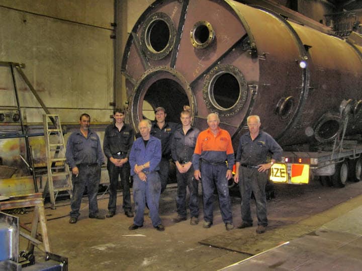 eat relationships with suppliers, clients and workers.
Developing and maintaining those great relationships are key to the company’s success in sectors which include mining, oil and gas, infrastructure, defence, water, chemical, aviation, automotive and maintenance.
The list of key clients is a long one and some are listed below:
Alcoa ARP
Coregas
CSR Limited
Endeavour Energy (Integral Energy)
Water Infrastructure Group
Visy Paper
One Steel
Blue Scope Steel
Nuplex Industries
Siemens
UEA Electrical
Air Liquide
Turnkey Engineering Group
Rheem
FJH have been the preferred supplier of Alcoa ARP for over 20 years – fabrication and general engineering for their Yennora site, providing furnace tubs, furnace components, scrap bins, loaders, general engineering and maintenance.
The company has also held the status of preferred supplier for over 15 years to Endeavour Energy. FJH maintain ALL substations from the Blue Mountains to Wollongong and the Central Coast. They fabricate, maintain and supply all components for Endeavour Energy’s substations, including the building of the actual substations and large switch yards plus performing general engineering and maintenance.
What is unique about FJH?
Greg states that one of the unique features of the company, is its old fashioned customer service.
However, FJH does have a large, fully fitted factory of over 600m². Most of the work is undertaken in the factory or on site; for fast turnaround. Another plus point is that very little outsourced, which allows for exceptional quality control.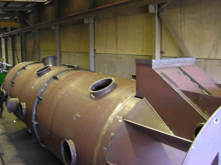
One other key area which makes FJH unique is that the company can (and regularly does) provide a high standard of troubleshooting to its customers.
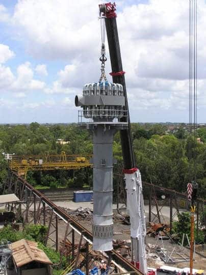
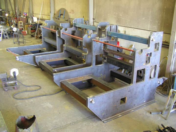
These unique attributes led to them being chosen by Turnkey Engineering Group to build 2 rotary furnaces.
These units were built in the factory and then transported to site. Each furnace barrel weighed in at 25 tonne and the sub-frames were 23 tonne each. There was a large amount of manpower involved in the project which took 3½ months to build and install on site.
How has the company changed over the years?
Greg states that evolving FJH by constantly keeping up to date with industry standards plus re-inventing the company ensures it is always able to offer fresh services which is in keeping with the demands of its clients.
Those changes and evolution of FJH have seen it continue to hold a strong piece of the market even after a lot of changes such as the turndown caused by the ‘Global Financial Crisis’ to the recent introduction of the Carbon tax.
While a lot of business are being moved overseas, Greg makes the point that due to the service provided, FJH customers have remained loyal, and have committed to use FJH rather than seeking cheaper alternatives or moving their fabrication procurement business overseas.
So what are the future plans for FJH?
Greg states that establishing new clients is a key driver for the company but key, is maintaining the great service to its existing clients and the unique heritage of FJH.
F J Hawney Pty Limited
Phone: (02) 9632-6749
Orders Fax (02) 9632-2667
Email: enquiries@fjhawney.com.au
Website: http://www.fjhawney.com.au
by Graham Fry

Welding Supervision Courses
March 1, 2014 in Welding Supervisors
Welding Supervisors Certificate Program
Complies with AS1796 Cert 10 Boilers & Pressure Vessels and Welding Supervisor AS 2214 Steel Structures
Who should do this course?
People wanting to qualify as a Welding Supervisor or requiring knowledge in this area are; Tradespeople, Technicians, Engineers, Sales Engineers, Foreman and leading hands, Workshop supervisors, Quality Managers and Expediters, Estimators, and Planning staff.

Units covered in this program
MEM05026C – Apply welding principles
The purpose of this unit is to apply basic metallurgy principles related to the general structure of metals and factors which influence weldability of a range of metals. It supports the basic metallurgy requirements for Certification under AS 2214 & AS1796.
The unit applies to the basic knowledge of metallurgy principles and the importance of base and weld metal compositions, for material type, welding process and procedure used. It identifies the areas that influence heat input on the deposited metal and heat-affected zone. It also identifies the areas for preheat, maintenance of interpass temperature and post weld heat treatment. The mechanical properties of welded joints and test used to determine mechanical properties and fabrication weldability tests are identified. Steel types for the fabrication of steel structures, pressure vessels & pipelines to meet the requirements of AS2214 & AS1796 certification.
MEM05024B Perform welding supervision
The purpose of this unit is to apply the welding process technology to meet Certification under AS1796 & AS2214. Competencies in this unit are based on wide knowledge of welding science, processes, procedure and technical requirements.
It covers the underpinning knowledge of welding terms, joints, positions and symbols, welding and allied processes, welding sequences, welding stresses and distortion and the effects of heat treatment on metal in relation to welding. This course also covers welding, planning an set up principles for a range of materials and processes, jigs, tools and plant facilities, as well as safe work practices and procedures and welding procedure specifications.
Interpret & Apply Codes & Specification in Welding Supervision Structural Steel & Pressure Equipment
The purpose of the above units is to interpret and apply codes and specifications used in the supervision of welding structural steel and Pressure Equipment in accordance with the current AS 2214 & AS1796. Competencies in these units are based on wide knowledge of welding processes, procedure and metallurgy, as well as application of appropriate codes & standards. The unit covers the underpinning knowledge of materials and consumables, heat treatments, qualification or welding procedure and welders, requirements for weld preparation, manufacturing, supervision and inspection and quality control
This Welding Supervisors Certification Program is delivered in a distance learning or online format for the Australian welding Industry which complies with the requirements for Welding Supervisor Certification to Australian Standards, AS1796 Cert 10 Pressure Equipment and AS2214 Structural Steelwork. Outsource Institute of Technology has formed an alliance with the Australian Welding Institute to independently examine and certify our graduates from this program.
If you’re interested in these highly sort after welding supervision courses, please log onto www.outsourceinstitute.com.au or call us on 1300 136 904.
by Graham Fry
AWI Offer
March 1, 2014 in Welding Certification, Welding Supervisors
Unprecedented offer to get AWI welding supervision qualifications
The AWI is providing an unprecedented offer to the industry and its members.
For those that have an existing welding supervision qualification through TAFE, another RTO’s or the WTIA we are offering you the opportunity to convert your qualifications into the AWI qualification.
It is easy to do, if you have evidence of the qualification and are willing to sit the exam all you do is apply to the AWI and sit the exam/s.
The intent is we will run them in all capital cities (based on numbers) at the end of June on the 20th and 21st.
So if you would like to take this opportunity and prove to the industry that you are capable of sitting any exam, here is your chance. If successful you will walk away dual certified.
If you want to sit the exam email admin@welding.org.au and we will forward you the application form, applications close June 6th 2014.

For more information contact: admin@welding.org.au
by Graham Fry
Progress of the AWI
March 1, 2014 in Welding Certification, Welding Supervisors
Progress of the AWI™
AWI™ Certification is now available for Welding Supervisors
A key responsibility of the AWI™ is to provide a credible, transparent and user friendly welding qualification system for its members. For some time now, the AWI™ has seen some great success in running a program for:
AS1796:2001
Certification for welders and welding supervisors – Certificate numbers 1 to 9.
The AWI™ has recently extended the program to include:
AS1796:2001
Certification for welders and welding supervisors Certificate number 10 plus;
AS2214:2004
Certification for welding supervisors – Structural steel welding.
The industry has been waiting for the return of a practical, relevant qualification, which is a cost competitive alternative to the offerings of the WTIA.
Wait no longer, the AWI™ are making this happen! AWI™ examination papers have been written and validated by industry experts that have extensive experience in the relevant disciplines. We have had some fantastic feedback from running these examinations are exampled below:
‘they are based much more on what we need to know in the workshop’
and
‘it was a very detailed exam but based on practical application of being a supervisor’.
The AWI™ has listened to industry, but more importantly -YOU – and have provided a certification system that measures the skills and knowledge of welding supervisors. The AWI™ is raising the bar on these important industry qualifications as well as giving you a quality alternative.
 AWI™ actively supports and promotes the AS 1796 and AS 2214 Welding Supervisors qualifications and encourages all members and the Metal Fabrication Industry to embrace these qualifications. AWI™ has established an alliance with a number TAFE Colleges around the country and takes pleasure in supporting and promoting these Colleges and programs and are now endorsing Welder Qualification AS 1796 Certificates 1 – 9, Welding supervisors AS1796 and AS2214.
Further information or Application forms are available through selected TAFE Colleges and from:
admin@welding.org.au
by Graham Fry
Hot Gas Welding of Plastics – Part 2 – Welding Techniques
March 1, 2014 in Job Knowledge
Introduction
Hot gas welding is a fabrication process for thermoplastic materials. The process uses a stream of heated gas, usually air, to heat and melt both the thermoplastic substrate and the thermoplastic welding rod. The substrate and the rod fuse together to produce a weld.
To ensure that welding takes place, adequate temperature and pressure must be applied to the rod, along with the correct welding speed and gun position. The overall welding operation consists of three main phases: substrate and rod preparation, welding and, finally, weld finishing. The final stage is not a necessary requirement and is dependent upon the application.
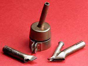
There are two types of hot gas welding for thermoplastic materials, round nozzle welding and speed welding. In the first, the welding gun is used with a round nozzle attached and in the latter, a second nozzle is attached to the round nozzle and is used to heat the welding rod at the same time as the operator applies welding pressure through the tip. Figure 5 shows a range of welding nozzles.
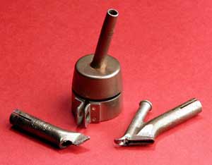
Fig.5. Plastics welding nozzles (left to right) tacking nozzle, round nozzle, high speed nozzle
Material preparation
The first phase of welding is preparation of the substrate materials and the welding rod. It is important to ensure that both are clean. This is helped by ensuring good storage procedures in a clean and dry environment. Before preparing the substrate it is important to check that any protective film is removed from the surface. Once the film is taken off, a scraper can be used to remove the surface layer of the material in the vicinity of the weld.
When selecting the materials for welding, the rod and substrate materials must be of the same polymer type.
If required, for example if the butt joint is used, an appropriate weld preparation should be added to the edge of the material before the scraping operation. Where the material thickness is less than 6mm, the preparation will generally be a 60° single-V chamfer. If the material thickness is greater than 6mm, then a 60° double-V preparation is used.
When the joint is in a T configuration, it is not necessary to prepare the edges with a chamfer, although it is still important to scrape both the substrate materials in the vicinity of the weld to remove any surface contamination.
Once the materials are prepared, the adjacent surfaces are abutted together and tacked into position using the tacking nozzle. Tacking should be sufficient to hold all the pieces of the fabrication together prior to welding.
It should be noted, however, that tacking alone should not be relied upon as the only method of holding the materials whilst welding. It is important to use additional clamps for this purpose. Once the substrates are assembled, the materials can be permanently welded together using either the round nozzle or speed welding techniques.
Round nozzle welding
In hot gas round nozzle welding, or hand welding as it is sometimes known, the rod is fed into the joint by hand. The nozzle is moved in a pendulum motion along the joint and up the welding rod, heating both the joint and rod as the weld is progressed. Figure 6 shows round nozzle hot gas welding.
When using this method it is important to maintain a constant pressure on the welding rod and a constant welding speed across the substrate. Generally, this can be helped by ensuring that you are in a comfortable position when welding. Round nozzle hot gas welding is generally only used where access to the joint is difficult, for example, around internal corners.
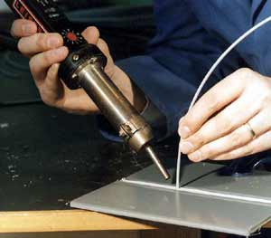
Fig.6. Hot gas round nozzle welding
Speed welding
In the hot gas speed welding technique, the rod is fed into the joint via a tube in the speed-welding nozzle (see Fig.4) attached to the round nozzle on the hot-gas welding gun.
The speed-welding nozzle also introduces hot air to the filler rod and to the joint. With this technique, the toe of the speed-welding nozzle is used to apply the pressure required for welding. Figure 7 shows hot gas speed welding.
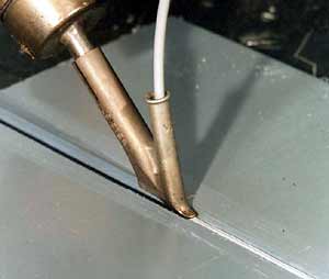
Fig.7. Hot gas speed welding
In order to achieve adequate welding pressure, the position of the operator’s hand on the welding gun handle is important. The hand holding the gun should be placed underneath the grip and forced downwards, applying pressure to the nozzle toe as welding progresses.
A light force should also be applied to the welding rod to ensure that it is fed through the tube at a constant speed. As with hand welding it is also important to feed the rod at a constant speed, maintain weld force using the nozzle toe and travel along the weld at a constant speed. Again, this is achieved by adopting a comfortable position when welding.
Producing the weld
In order to achieve a weld, the joint must be sufficiently filled with welding rod and each welding run must be adequately fused to both the next run and the parent material.
Once the materials are tacked (see preparation), the first weld run can be placed into the base of the joint. The temperature of the welding gun should be set in accordance with the guidelines produced by the materials manufacturer.
The manufacturers’ guidelines on welding pressure, airflow, and welding speed should also be followed. The base run should have good root penetration and, in the case of polypropylene, a small ‘side wash’ (see Fig.8)
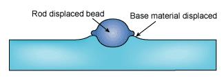
Fig.8. Section through polypropylene weld showing ‘side wash’
The welding rod should not display signs of degradation (brown spots) or overheating. In the case of PVC, overheating is signified by a shiny smooth surface on the welding rod.
In the case of polypropylene, ‘splattering’ at the edge of the weld indicates overheating of the material during welding.
Between each run, as the joint is filled, a chisel or scraper is used to produce a small V preparation for the subsequent adjacent weld runs to be positioned in. This is shown in Fig.9.
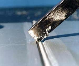
Fig.9. Chisel between hot gas weld runs
The number of runs needed will be determined by the thickness of the substrate being welded. The weld is finished when the top series of runs is above the surface of the parent material. These runs are known as capping runs.
Finishing the weld
In some circumstances it may be necessary to remove the weld capping runs and leave a flush surface, for example where an aesthetic finish to the joint is required. These capping runs can be removed using either a hand grinder or scraper until the weld is flush with the surface of the substrate material. This can be done on both sides of the weld.
Copyright © TWI Ltd 2014
The content of this article was correct at the time of publication. For more information visit: www.twi-global.com
by Graham Fry
Hot Gas Welding of Plastics – Part 1 – The Basics
March 1, 2014 in Job Knowledge
Hot gas welding of plastics:
Part 1 – The basics
Process background
Hot gas welding is a fabrication process for thermoplastic materials. The process, invented in the mid 20th century, uses a stream of heated gas, usually air, to heat and melt both the thermoplastic substrate material and the thermoplastic welding rod. The substrate and the rod fuse to produce a weld (See Fig 1 and 2).
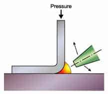
Fig.1. Hot gas hand welding nozzle motion and rod angle
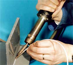
Fig.2. Hot gas hand welding
To ensure welding takes place, adequate temperature and pressure must be applied to the rod, along with the use of the correct welding speed and gun position.
The weld quality, since this is a purely manual technique, is dependent on the skill of the welder. Typical applications include chemical storage vessels, ventilation ducting and repair of plastic mouldings such as car bumpers.
Welding materials
There are two groups of plastic materials; thermoplastics and thermosets. The hot gas welding technique is only applicable to those plastic materials that can be heated and melted repeatedly, namely thermoplastics. When a thermoplastic is heated, the molecular chains become mobile within the material and allow it to melt and flow. Thermosets are a group of plastic materials in which the molecular chains form cross-links. These cross-links, formed by a chemical reaction, prevent the molecular chains becoming mobile when heat is applied. Although many thermoplastics can be welded by this process, the most common are polypropylene, polyethylene, PVC and some fluoropolymers such as PVDF, FEP and PFA.
Extruded rod and sheet are the most commonly used raw materials for the manufacture of fabricated plastic products. It is of utmost importance when fabricating plastics that the welding rod and the sheet are of identical material and chemical type.
For example, although it is possible to weld polypropylene homo-polymer to polypropylene random block copolymer, the strength of the weld will be reduced significantly. It is also important to check the quality of the welding rod prior to use, since air bubbles within the rod can form during the extrusion process.
These will lead to voids in the weld. Welding rods will typically be either three or four millimetres in diameter.
Welding equipment
The equipment used for hot gas welding consists of an air supply, a handle with sturdy grip, a heating chamber with temperature control to produce the hot gas and a nozzle where the heated gas leaves the welding gun in order to heat the plastic rod and substrate. (Fig.3)
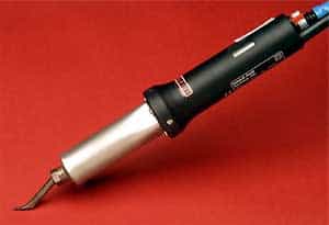
Fig.3. Hot gas welding gun
A fan, either incorporated into the welding gun handle or positioned remotely and connected to the gun, provides the air supply. It is also possible to use compressed gas from bottles, for example, air or nitrogen. Whichever gas supply is used, it is important that it is clean and dry, since dirt and moisture will contaminate the weld.
The gun temperature is set via a dial on the handle, with some welding guns showing the temperature of the air stream on a digital read-out also on the handle. It is good practice to measure the gas temperature consistently using a digital thermometer, for example, with the thermocouple tip placed 5mm inside the welding gun nozzle.
The front end of the welding gun allows interchangeable welding nozzles to be fitted depending on the type of welding needed.
Three nozzle types are most commonly used, the tacking nozzle, the round nozzle and the high-speed nozzle (Fig.4).
Fig.4. Plastic welding nozzles ( left to right) tacking nozzle, round nozzle, high speed nozzle
The tacking nozzle, as the name suggests, is used to tack the materials together before welding. The round nozzle allows the welder to heat the rod and substrate without physical contact with either and is useful for welding in areas with difficult access. This is less commonly used than the high-speed welding nozzle where the toe of the nozzle contacts the welding rod and allows the welder to put pressure on both the rod and the substrate material whilst welding.
Along with correct temperature, the pressure ensures that there is adequate fusion between the welding rod and the substrate material. In addition to the welding gun, several tools are needed. These are a coarse tooth file, router and hand grinder for edge preparation, a scraper for removal of the material surface around the weld and a wire brush for cleaning the nozzle.
Also, wire cutters are required for cutting the welding rod and a jigsaw for cutting the substrate material.
Welding parameters
There are four main welding parameters in the hot gas welding process: temperature, pressure, welding speed and gun position.
Since the process is manual, it is important that the welder has a good understanding of the need to ensure that all four of these parameters are correct and controlled during the welding operation.
Temperature is the most important of the four parameters, since the temperature at the interface between the rod and the substrate is not only controlled by the setting on the gun, but also by the gun travel speed and the gun position with respect to the substrate. Typically, the temperature for welding is set between 80 and 100°C above the melting point of the material being welded.
The gun travel speed is normally between 0.1 and 0.3m/min, again, depending upon the material being welded.
The welding pressure is applied via the toe of the welding nozzle and is achieved by holding the welding gun grip firmly and pushing down into the weld. For round nozzle welding, pressure is applied manually from the welding rod. The correct welding pressure is easier to achieve using welding guns with the fan separate to the gun since a firmer grip around the handle can be achieved. The force applied to the welding rod would typically be between 15 and 30N. Practical welding details are given in Part 2 – welding techniques
Weld quality
As a manual process, weld quality is dependent on skill. There is no recognised non-destructive technique, that conclusively shows the presence of defects in plastic welds that could lead to weld failure. Therefore, it is recommended that good quality welder training is received and that welder certification is adopted.
The European Standard (EN13067) sets out the criteria for plastic welder approval. It details a scheme where the welder undergoes both a theoretical and a practical test and the welder, upon successful completion, is awarded a certificate of approval in the specific material categories taken in the test. Certification lasts for two years with a further two years prolongation, effectively giving the welder an approval certificate for four years before requiring a full retest.
by Graham Fry
Weld Fusion vs Penetration
March 1, 2014 in Articles

Weld Fusion vs penetration
I have heard some people say that with all welding, you must have deep or maximum penetration into the base plate in order for a weld to be strong. If you have shallow penetration, the weld is weaker. The deepest possible weld penetration is always best. Are these statements accurate?

Fig 1 Common Joint and Weld Types
Arc welding is taking two or more separate pieces of metal and joining them into one continuos or homogeneous section. You achieve coalescence, which means to blend or come together. In other words, the purpose of arc welding is to achieve fusion between the initially separate pieces of metal. The American Welding Society (AWS) defines fusion as “the melting together of filter metal and base metal (substrate), or of base metal only which results in coalescence: (ANSI/AWS A3.0 Standard Welding Terms and Definitions). Fusion occurs when you have atomic bonding of the metals. The molecules of each separate piece of metal and the filter metal bond together when you have 1)atomic cleanliness and 2)atomic closeness (see FIGURE 2). This occurs with arc welding such that the atoms of each piece of metal bond together with shared electrons to become one solid or homogeneous piece of metal.
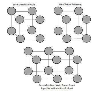
Figure 2 Atomic Bonding
Now on the other hand, penetration, or properly termed depth of fusion, is defined by AWS as, “The distance that fusion extends into the base metal or previous pass from the surface melted during welding”. A cross section of a weld (particularly when etched) will show you the penetration profile of the weld, including the depth and width of penetration (see examples in Figure 3 and 4, which also name and highlight the various parts of a fillet and groove weld).
To achieve the proper weld strength, all welding requires complete fusion to occur between the pieces of metal and filler metal, but not all joints require a large depth of fusion or deep penetration. As long as you have achieved complete fusion between the filler metal and the base plates (and when appropriate, the steel backing bar), you have successfully joined the metal together into one homogenous piece. It does not matter if you have deep penetration or shallow penetration.
Theoretically (but not realistically), you could even have complete fusion to just the depth of a few molecules and still have welded the pieces together.
As an example, refer to the T joint and fillet weld in Figure 3, the required weld strength is achieved by having complete fusion and by producing the proper fillet weld size (measured by either the leg length or theoretical throat length) for a given weldment.
The appropriate weld size needed to achieve adequate weld strength is determined by the design engineer during the design stage. How this is determined is beyond the scope of this article. However, as the fabricator, as long as you make the proper sized weld per the design specification and achieve complete fusion between the filler metal and base plates, including the root, you have produced a weld of sufficient strength. Weld strength is not determined by the level of penetration into the base plates.

Figure 3 Part of a Fillet Weld
As another example, refer to the butt joint and complete joint penetration (CJP) single V groove weld in Figure 4. Proper weld strength for a CJP groove weld is achieved by having complete weld fusion and by using the correct strength filler metal (i.e. one that is of a least matching strength to the base metal). Again, weld strength is not determined by the level of penetration into the base plates.
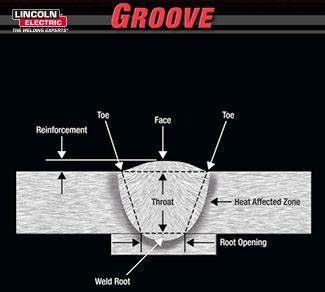
Figure 4 Parts of a Groove Weld (Butt Joint)
The need to achieve complete fusion has been emphasized in this article.
That is because a problem can arise if you have a lack of fusion in any part of the joint. This can be a discontinuity with the sidewall fusion, properly termed joint penetration, or fusion at the root, properly termed root penetration. Incomplete fusion can become a weld defect area, which can affect the weld strength and ultimately lead to weld failure.
Figure 5 shows examples of a acceptable and unacceptable weld profiles.
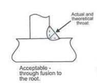
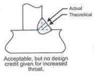
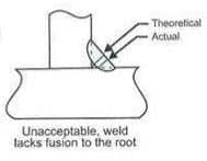 Figure 5 Three Fillet weld profiles
While not necessarily related to weld strength, there are situations in which deeper weld penetration can be beneficial. Here are three examples:
Benefit: As stated earlier, you must achieve complete fusion at the root of weld joint. If the electrode is not aimed properly at the root, the arc length or contact tip to work distance (CTWD) is not held at a consistent distance and/or proper procedures or set up are not used, then lack of fusion issues at the root are more likely to occur.
These factors are controlled by the operator’s welding skills, with less experienced welders more likely to have lack of fusion issues, When you have a welding procedure that produces a deeper weld penetration (and a resulting wider penetration profile), you increase the chances of still achieving complete fusion at the root, even with welders that have limited skills. A deeper and broader penetration profile covers a bigger area.
Thus you are more likely to still hit the root (i.e. achieve fusion) even if the arc is not focused directly at it.
Benefit: Figure 6 shows examples of CJP groove welds in a butt joint with a root face dimension (i.e. the square edge or non-bevelled portion of the plate edges in a butt joint).
These joints will be welded from the first side (with one or more passes, depending on plate thickness). Then typically the weldment is flipped over and welded form the second side (again, with one or more passes).
To achieve complete joint penetration, the plates must be beveled, as in the double V joint shown in the top picture. Or if it is a square edge joint (shown in bottom picture), then after the first side is welded, the second side of joint must be back gouged to sound weld metal. Then the second side is welded.
If welding procedures that produced a deeper weld penetration were used,, the the depth of the joint bevels would not need to be as deep, making the root face longer. Or in the case of square edges, not as much base plate on the second side would need to be removed by back gouging before sound weld metal was reached. In either case, the volume of weld metal required to fill the joint would be reduced.
This reduces both the amount of filler metal required to fill the joint and the welding time. Less welding would also reduce potential plate warpage issues.
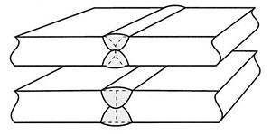
Figure 6 Joints Requiring Penetration
Benefit: For fillet welds with a flat face and even leg sizes, the distance from the weld face to the root is called the theoretical throat. If you achieve fusion beyond the root, then the actual or effective throat length increases (see Figure 3 for identification of the theoretical and actual throats).
Generally no design credit of extra weld strength is given to normal root penetration. However, if significant and consistent root penetration can be achieved, which significantly increased the effective throat depth, then the fillet leg size can be reduced without sacrificing weld strength (see example in Figure 7).
Deeper weld penetration does not produce a fillet weld with more weld strength. Rather, it allows a smaller fillet weld to be made with the same strength level as a larger fillet weld made with less weld penetration. Smaller fillet welds decrease the amount of weld metal needed, and may even allow for increased travel speeds This benefit could be potentially realized by using the Submerged Arc Welding (SAW) process, known for its deep penetration capabilities. Other arc capable of producing the deeper penetration level on a consistent basis, so this concept may not always be applicable. this Welding Innovations article from the James F Lincoln Foundation website discusses this topic in more detail.

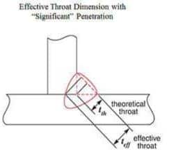
Figure 7 Two Diagrams Showing Greater Effective Throat Produced with Significantly Deeper Weld Penetration
Limitation: Deep penetration can be troublesome when burn-through is a concern. When welding on thins material, such as gauge thickness sheet metal. too much penetration can cause the weld to burn all the way through the joint and fall out the bottom. In other cases, a thin root pass is made in an open root joint (e.g. pipe joint). If the second pass has too much penetration, burning through the root pass can be an issue.
Limitation: If penetration is too deep, centerline cracking (a form of hot cracking) may become an issue. see Figure 8 for an example of a centerline crack in a fillet weld. a balance must be maintained between the depth of penetration and the width of the root pass. the depth to width ratio (W?D ratio) should not exceed 1 to 1.2.
This keeps the shape of the weld fairly uniform. As the weld metal solidifies, the shrinkage stresses are thus fairly uniform in all directions. However, if the weld is significantly deeper than wide, then the shrinkage stresses are unequal and the weld will crack in the centre of the bead as a result.
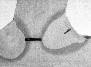
Figure 8 Deep Penetration Weld with Centerline Crack due to Insufficient W/D Ratio
Limitation: Too much admixture with the base plate may also be a problem with deep penetration welds. As penetration increases, so does the volume of base plate that is melted and combined with the filler metal in the resulting weld puddle.
This can possibly add additional elements into the weld puddle that makes the weld more crack sensitive. Examples would include welding on free machining grades of steel with higher levels of sulphur, phosphorus and/or lead. These softer elements have lower melting (and solidification) temperatures than steel.
So in the liquid weld puddle, they tend to migrate to the center of the weld where they are the last elements to solidify,
This high concentration of softer elements in the center of the weld bead often leads to centerline cracking from the solidification shrinkage stresses of the weld.
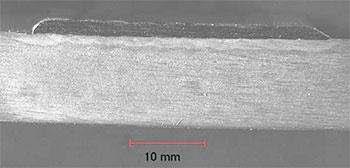
Figure 9 Weld with Shallow penetration
Additionally, in the case of hardfacing or overlay applications, deeper penetration may dilute the weld deposit chemistry and potentially decrease its resulting wear resistance properties.
Overlay welds are simply “bead on plate” welds. Figure 9 shows a weld overlay with minimum penetration and thus minimum admixture between the weld metal and base plate
Figure 10 shows a bead on plate weld with deeper penetration and thus much more admixture between the weld metal and base plate.

Figure 10 Weld with Deep Penetration
by Graham Fry
GF Engineering
January 1, 2014 in Articles
GF Engineering is an ISO 9001 and ISO 3834.2 accredited company based in Naval Base, Western Australia specialising in carbon, stainless and exotic steel piping for the Oil and Gas, Mining and Power Generation Sectors. We also offer fabrication of Pressure Vessels as well as both heavy and light structural works including; chutes, supports, trestles, hand rails, platforms and stair cases. GF Engineering is a pioneer of Orbital TIG Technology and can provide demonstrations for interested clients. We also offer a highly specialised and experienced site installation and fabrication team. Visit http://www.gfengineering.com.au for further details.
by Graham Fry
Progress of AWI
January 1, 2014 in Certifications
Progress of the AWITM
Certification
A key responsibility of the AWI™ is to provide a credible, transparent and user friendly welding qualification system for its members. To do this the AWI™ earlier established an Educational and Certification Working Group (E&C) to meet the following primary objectives:
- To undertake, arrange and promote education, training, qualification and certification for the benefit of members of the Institute and the welding industry as a whole
- To work closely with Australian TAFE bodies, Registered Training Organisations (RTO’s) related government agencies and departments to enhance National training agendas.
AWI™ actively supports and promotes the AS 1796 and AS 2214 Welding Supervisors qualifications and encourage all members and the Metal Fabrication Industry to embrace these qualifications. AWI™ has established an alliance with a number TAFE Colleges around the country and takes pleasure in supporting and promoting these Colleges and programs and are now endorsing Welder Qualification AS 1796 Certificates 1 – 9, Welding supervisors AS1796 and AS2214.
Application forms are available through selected TAFE Colleges and from admin@welding.org.au.
Compliance to AS/NZS ISO 3834 – AWI™ Guidance for Fabricators
The AWI™ has received some information revealing a high degree of confusion regarding Certification for AS/NZS ISO 3834 Quality Requirements for Fusion Welding. Therefore we have decided to re-print a previous guidance note.
Certification
Certification for AS/NZS ISO 3834 Quality Requirements for Fusion Welding is not required. As a standard, AS/NZS ISO 3834 simply lays down requirements for compliance. It is not a mandatory standard to be enforced by law.
A fabricator wishing to comply with 3834, can simply consider the relevant sections of the standards and satisfy themselves of their compliance, which they can then declare to potential customers. As part of this declaration, they are required to detail the documents used and the controls implemented.
Developing a competitive edge
Compliance with 3834 provides a global recognition of a fabricator’s capability, can reduce costs associated with rework, wastage etc. and can enhance a company’s ability to sell its products in both domestic and international markets.
 Improved client confidence
AS/NZS ISO 3834 contains three levels of quality requirements and the appropriate level for your company will depend on the degree of complexity of the Company’s welding operations.
In an endeavour to increase your company’s capability in the welding quality market, AWI™ can assist in 3834 compliance after completion of our application document by:
- A review of the application documentation.
- AWI™ will conduct an assessment of your company’s current quality system, procedures etc.
- Determining which level of welding quality is appropriate for your company and which is in the most practical for your company to achieve and maintain.
The outcome of the AWI™ assessment will determine if your company’s system is in need of add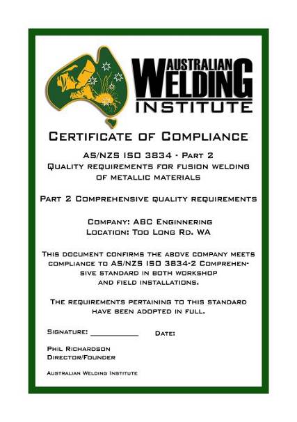 itional controls and procedures or is already successful in compliance to the relevant section/s of 3834.
We can assist in building a 3834 document structure and develop the required controls and procedures or fill in any gaps to your existing quality structure.
Successful applicants will be issued with a “Certificate of Compliance” indicating which level of compliance has been achieved. Certification can be addressed at a later stage if the company decides it wants to address this option.
For further details contact:
Phil Richardson on: 0438 991 860 or contact admin@welding.org.au
AWITM Certification assists member achieve their goal
I was given a start in engineering sector by my current employer GF Engineering in 2007 fresh off the streets with no prior experience. Initially recruited for the drawings department to produce shop detail drawings and isometrics, I was based in the same office as our Welding Supervisor (Trent Groves). GF Engineering invested the time and patience in me and provided the necessary in house training to develop me within my role.
Over the years I worked closely with Trent and learnt many aspects of the industry and the steps involved to produce a high standard product. I also began to learn the various codes and client specifications that we were working to. After a 2 year stint in Project Management, I moved back into the Quality office to help reduce the workload of Trent – where I became more involved in the day to day running of the Quality Department.
I attended Challenger Tafe once a week at night after work for 2 years, completing the Welding Supervisors course, where I gained the necessary theory and practical experience to be eligible to sit the Supervisors Exams.
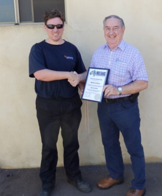
Bodie Logan and Phil Richardson
Trent eventually moved on from GF in mid-2012 and I was asked to take over his role as Supervisor and Quality manager. Over the next 18 months I began to grow in confidence in my abilities and knowledge and contacted the AWI in November 2013 to sit my AS2214 Supervisors examination.
The ‘A’ paper was detailed and covered a wide range of aspects from the industry including; Welding Processes and Technology, Metallurgy, Quality Processes and Safety. Whilst in depth, all questions were relevant to today’s practices and standards. The ‘B2’ paper was based on AS 1554 Parts 1 and 2 and again was in depth, but designed in such a way that someone with sound knowledge and experience in the codes could manage all the questions within the timeframe allocated.
I thank that AWI for being flexible and allowing me to sit both the papers back to back on the one day. It was an enjoyable process and the feedback and level of service from the AWI has been outstanding.
I look forward to sitting the AS1796 Supervisors exams through them in the near future.