To confirm that a weld has been made to specification it is usually required to measure and often document the parameters that have been used. For arc welding the main parameters are as follows:
- Welding current
- Arc voltage
- Travel speed
These parameters can be used to calculate the heat input, which is derived from the arc energy.
The other parameters which may be measured and recorded are as follows:
- Wire feed speed (for MIG/MAG) and other processes with a filler wire
- Gas flow rate (shielding, backing and plasma)
- Temperature (pre-heat, inter-pass and post-weld heat treatment)
In most cases the mean values of the parameters over the time of the weld can be recorded and used to calculate heat input.
A simple meter can be used for this, but it is better for quality assurance to have documented values. A number of instruments exist which have been specifically designed for this purpose.
Generally, they provide a paper printout with mean values over a second or so. Some of these instruments allow the length of the weld to be input so that arc energy (kJ/mm) can be calculated.
When measuring voltage and current it is important to do so correctly.
Although current can be measured anywhere in the circuit, Figure 1, it is important to ensure that all the current passes through the cable and is not, for example, conducted elsewhere through the component or through a leakage path to earth.

Fig. 1. Current weld measuring technique, ‘A’ showing the connection for the sensor
Current is normally measured by a Hall effect probe clipped around the cable. The current rating and accuracy of the probe needs to be taken into account.
Voltage measurement is a bit more difficult to get right as the voltage will vary depending where the connections are made. For true arc voltage, it is important to measure as close to the arc as possible, Figure 2.
For MIG/MAG, a connection on the drive rolls, back at the wire feeder, will suffice. However, the voltage measured across the arc will be lower than that measured across the power source terminals, possibly by several volts, depending on the length and diameter of the welding cables and the amplitude of the welding current.
 Connection to the back of the TIG torch; b) Connection to the back of the MIG gun")
Fig. 2. Voltage measuring technique a) Connection to the back of the TIG torch; b) Connection to the back of the MIG gun
Care should be taken when measuring arc voltage in TIG welding as the high voltage used for starting the arc may damage the instrumentation unless it is specifically designed for arc monitoring.
Some standards now require heat input to be calculated from instantaneous values and this requires an instrument that can accurately record the waveform of the voltage and current and perform the calculation up to 5,000 times per second or more.
An example of such an instrument is shown in Figure 3. Several other manufacturers provide similar instruments.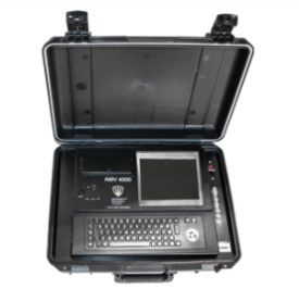
Such instruments can record and display the current and voltage waveform from pulsed TIG and MIG/MAG processes including controlled dip transfer and multi-pulse techniques.
Wire feed speed can be measured by clipping a tachometer to the wire or by attaching a sensor to the wire feed drive rolls. Temperature is measured using a thermocouple or resistance temperature detector (RTD) probe in contact with the surface or, alternatively, an infrared non-contact device.
Although gas flow can be measured with a bobbin type gauge, for recording the value a mass flow type instrument is required.
Limits can be set (typically +/-10%) to indicate if the parameters have deviated outside of the procedure and statistical process control (SPC) can be used to stop or correct a process before problems occur.
Calculating weld volume and weight
Calculating the volume of a weld is one of the first steps to be taken when estimating the cost of making a weld.
With this information, and knowing the deposition rate of the process, it is possible to determine the arc time (the length of time that an arc is burning and depositing weld metal) and the amount of welding consumables required to fill the joint. Both of these are required in order to calculate the cost of making the weld. Costing will be dealt with in future Job Knowledge articles.
Determining the volume of a weld requires some knowledge of basic geometrical calculations to determine the area of the weld and multiply this figure by its length. The first step then is to calculate the cross sectional area of the joint.
With a fillet weld or a 45° single bevel joint this is relatively simple but the calculations become lengthier as the weld preparation becomes more complex. Fig.1 illustrates how simple this calculation is for an equal leg length fillet weld; the area of such a weld is half the square of the leg length, Z. When using this formula do not forget that welders seldom deposit precisely the size of weld called up on the drawing or in the welding procedure and that there may be some excess weld metal on the face of the weld.

Fig.1. Area of an equal leg length fillet weld
An asymmetrical fillet weld is a little more difficult; the area of a triangle is given by the base Z2 times the height Z1divided by 2 so when a fillet weld is deposited with unequal leg lengths the area can be calculated from multiplying the throat, a, by the length of the face I and divided by 2 as illustrated in Fig.2.

Fig.2. Area of an unequal leg length fillet
Turning now to butt welds, the calculations become a little more complex.
There are three factors that determine the volume of the weld in a single V butt weld. These are the angle of the bevel, b, the excess weld metal and the root gap, g, as illustrated in Fig 3. To calculate the area of this weld we need to be able to add together the areas of the four components illustrated in Fig.3.

Fig.3. The four areas of a single-V butt weld
The dimension ‘c’ is given by (tan b x t); the area of a single red triangle is therefore t(tan b x t)/2.
The total area of the two red regions added together can be calculated using the formula 2t(tan b x t)/2 or t(tan b x t).
The width of the weld cap, w, is given by W = 2(tan b x t) + g.
The area of the excess weld metal is approximated by the formula (W x h)/2.
The area provided by the root gap by g x t.
The bevel angles, b, most often used are 10° = (tan 0.176), 15° = (tan 0.268), 22.5° = (tan 0.414) 32.5° = (tan 0.637) and 45° = (tan 1.00).
As will become obvious when the weight is calculated, it is easier to ensure that the decimal point is in the right place if centimetres are used in the calculations rather than millimetres.
As a worked example, if the weld is in a plate 2.5cm thickness, 0.3cm root gap, 65° included angle (b = 32.50°; tan 32.5° = 0.637) and with a cap height of 0.2cm we have:
- c = tan32.5 x 2.5 = 0.637 x 2.5 = 1.59cm
- w = 2(0.637×2.5) + 0.3 = 3.485cm so the area of the cap = (3.485×0.2)/2 = 0.348 sq. cm.
- area of the orange area = 0.3 x 2.5 = 0.75 sq.cm.
- area of the two red areas = 2 x (1.59 x 2.5)/2 = 3.97sq.cm.
This gives a total area of 5.07sq cm. The volume can then be calculated by multiplying the length of the weld by the area – ensuring that this length is also given in centimetres!
Conventionally, the volume is often expressed in cubic centimetres (cu.cm). per metre so in this example the volume is 507 cu. cm/metre.
To obtain the weight of weld metal this figure is then multiplied by the density of the alloy. Table 1 gives the density of some of the more common alloys in gm/cu.cm. Note that with some alloys the alloying elements can change the density quite significantly.
| Alloy | Density (gm/cm3) |
| iron | 7.87 |
| 0.25% carbon steel | 7.86 |
| 12%Cr steel | 7.70 |
| 304 stainless steel | 7.92 |
| nickel | 8.90 |
| 80/20 Ni.Cr | 8.40 |
| 625 type alloy | 8.44 |
| copper | 8.94 |
| 70/30 brass | 8.53 |
| 7% Al bronze | 7.89 |
| aluminium | 2.70 |
| Al 5052 | 2.65 |
| Al 7075 | 2.8 |
Table 1. Densities of some of the more common alloys.
The weight of weld metal to fill one metre length of the joint described above would therefore be; in carbon steel (507 x 7.86) = 3985gms or 3.98kgs/metre; in a 5XXX series aluminium alloy (507 x 2.65) = 1343gms, 1.34kgs/metre.
Calculating the weight of weld metal in double sided V-joints uses the same approach by dividing the weld into its individual ‘V’s and adding the products.
A J-preparation, however, adds another area into the equation; that of the half circle at the root of the weld, see Fig.4. The formulae given above to calculate ‘c’, the area of the two red components and the excess weld metal remain unchanged but the width of the cap must be increased by 2r.
There are also the two areas, ‘A’ and ‘B’, to calculate and the two white root radius areas to be added to the total.
")
Fig.4. Single ‘U’ preparation (other notation as in Fig.3)
The relevant formulae are thus:
- the dimension ‘c’ is given by (tan b x (t-r)); the total area of the two red regions is therefore given by the formula 2((t-r)(tan b x (t-r))/2 or ((t.-r)(tan b x (t-r)).
- the width of the weld cap, w, is given by w = 2(tan b x (t-r)) + g +2r.
- the area of the excess weld metal is given by the formula (w x h)/2.
- the area ‘A’ is (t-r) x (2r +g).
- the area ‘B’ is g x r.
- the root radius area is (πr2)/4
For a double-U preparation it is necessary to calculate the areas of both sides and add these together.
Having calculated the weight of weld metal required to fill a weld preparation it is then possible to calculate the weight of filler metal required (these two figures are not necessarily the same) and to estimate the time required to deposit this weld metal; both essential in order to arrive at a cost of fabricating the weld. This will be covered in future Job Knowledge articles.
This article was written by Gene Mathers.
Copyright © TWI Ltd 2014
The content of this article was correct at the time of publication. For more information visit
www.twi-global.com