
Notched bar or impact testing – Part 1
Before looking at impact testing let us first define what is meant by ‘toughness’ since the impact test is only one method by which this material property is measured.
Toughness is, broadly, a measure of the amount of energy required to cause an item – a test piece or a bridge or a pressure vessel – to fracture and fail. The more energy that is required then the tougher the material.
The area beneath a stress/strain curve produced from a tensile test is a measure of the toughness of the test piece under slow loading conditions. However, in the context of an impact test we are looking at notch toughness, a measure of the metal’s resistance to brittle or fast fracture in the presence of a flaw or notch and fast loading conditions.
It was during World War II that attention was focused on this property of ‘notch toughness’ due to the brittle fracture of all-welded Liberty ships, then being built in the USA.
From this work the science of fracture toughness developed and gave rise to a range of tests used to characterise ‘notch toughness’ of which the Charpy-V test described in this article is one.
There are two main forms of impact test, the Izod and the Charp test.
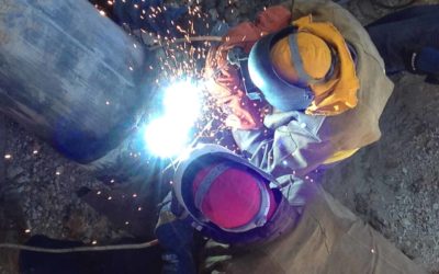
Both involve striking a standard specimen with a controlled weight pendulum travelling at a set speed. The amount of energy absorbed in fracturing the test piece is measured and this gives an indication of the notch toughness of the test material.
These tests show that metals can be classified as being either ‘brittle’ or ‘ductile’. A brittle metal will absorb a small amount of energy when impact tested, a tough, ductile metal a large amount of energy.
It should be emphasised that these tests are qualitative, the results can only be compared with each other or with a requirement in a specification – they cannot be used to calculate the fracture toughness of a weld or parent metal, such as would be needed to perform a fitness for service assessment.
Fracture toughness tests that can be used in this way are covered in other Job Knowledge articles.
The Izod test is rarely used these days for weld testing having been replaced by the Charpy test and will not be discussed further in this article.
The Charpy specimen may be used with one of three different types of notch, a ‘keyhole’, a ‘U’ and a ‘V’.
The keyhole and U-notch are used for the testing of brittle materials such as cast iron and for the testing of plastics.
The V-notch specimen is the specimen of choice for weld testing and is the one discussed here.
The current ISO Standard for Charpy testing is ISO 148-1:2009 and the American Standard is ASTM E23.
The standards differ only in the details of the strikers used. The standard Charpy-V specimen, illustrated in Fig.1. is 55mm long, 10mm square and has a 2mm deep notch with a tip radius of 0.25mm machined on one face.
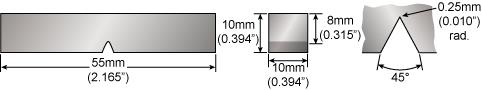
Fig.1. Standard Charpy-V notch specimen
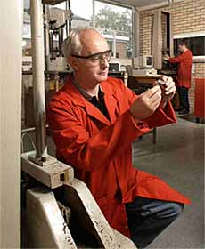
To carry out the test the standard specimen is supported at its two ends on an anvil and struck on the opposite face to the notch by a pendulum as shown in Fig.2.
The specimen is fractured and the pendulum swings through, the height of the swing being a measure of the amount of energy absorbed in fracturing the specimen. Conventionally three specimens are tested at any one temperature, see Fig.3, and the results averaged.
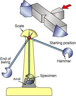
Fig.2. Charpy testing machine
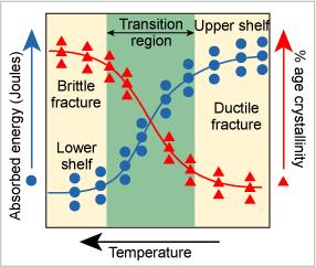
Fig.3. Schematic Charpy-V energy and % age crystallinity curves
A characteristic of carbon and low alloy steels is that they exhibit a change in fracture behaviour as the temperature falls with the failure mode changing from ductile to brittle.
If impact testing is carried out over a range of temperatures the results of energy absorbed versus temperature can be plotted to give the ‘S’ curve illustrated in Fig.3.
This shows that the fracture of these types of steels changes from being ductile on the upper shelf to brittle on the lower shelf as the temperature falls, passing through a transition region where the fracture will be mixed.
Many specifications talk of a transition temperature, a temperature at which the fracture behaviour changes from ductile to brittle.
This temperature is often determined by selecting, quite arbitrarily, the temperature at which the metal achieves an impact value of 27 Joules – see, for example the impact test requirements of EN 10028 Part 2 Steel for Pressure Purposes.
What the curve shows is that a ductile fracture absorbs a greater amount of energy than a brittle fracture in the same material. Knowing the temperature at which the fracture behaviour changes is therefore of crucial importance when the service temperature of a structure is considered – ideally in service, a structure should operate at upper shelf temperatures.
The shape of the S curve and the positions of the upper and lower shelves are all affected by composition, heat treatment condition, whether or not the steel has been welded, welding heat input, welding consumable and a number of additional factors.
All the factors must be controlled if good notch toughness is required. This means that close control of the welding parameters is essential if impact testing is a specification requirement.
Austenitic stainless steels, nickel and aluminium alloys do not show this change in fracture behaviour, the fracture remaining ductile even to very low temperatures. This is one reason why these types of alloys are used in cryogenic applications.
In addition to the impact energy there are two further features that can be measured and may be found as a requirement in some specifications. These are percentage crystallinity and lateral expansion.
The appearance of a fracture surface gives information about the type of fracture that has occurred – a brittle fracture is bright and crystalline, a ductile fracture is dull and fibrous.
Percentage crystallinity is therefore a measure of the amount of brittle fracture, determined by making a judgement of the amount of crystalline or brittle fracture on the surface of the broken specimen.
Lateral expansion is a measure of the ductility of the specimen. When a ductile metal is broken the test piece deforms before breaking, a pair of ‘ears’ being squeezed out on the side of the compression face of the specimen, as illustrated in Fig 4. The amount by which the specimen deforms is measured and expressed as millimetres of lateral expansion. ASME B31.3 for example requires a lateral expansion of 0.38mm for bolting materials and steels with a UTS exceeding 656N/mm2, rather than specifying an impact value.
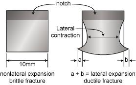
Fig.4 Lateral expansion
Notched bar or impact testing. Part II
The previous article looked at the method of Charpy-V impact testing and the results that can be determined from carrying out a test.
This next part looks at the impact testing of welds and some of the factors that affect the transition temperature such as composition and microstructure. Within such a short article, however, it will only be possible to talk in the most general of terms.
Welding can have a profound effect on the properties of the parent metal and there may be many options on process selection, welding parameters and consumable choice that will affect impact strength.
Many application standards therefore require impact testing to be carried out on the parent metal, the weld metal and in the heat affected zone as illustrated in Fig.5 which is taken from BS PD 5500 Annex D.
The standards generally specify a minimum impact energy to be achieved at the minimum design temperature and to identify from where the specimens are to be taken.
This is done in order to quantify the impact energy of the different microstructures in the weld metal and the HAZs to ensure that, as far as possible, the equipment will be operating at upper shelf temperatures where brittle fracture is not a risk.

Fig.5. PD5500 App D. location of Charpy specimens in weld HAZ
These application standards may be supplemented by client specifications that impose additional and more stringent testing requirements, as shown in Fig.6 taken from an oil industry specification for offshore structures.
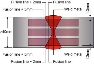
Fig.6. Offshore client requirements
The positioning of the specimens within a weld is extremely important both in terms of the specimen location and the notch orientation. A specimen positioned across the width of a multi-pass arc weld will probably include more than one weld pass and it’s associated HAZs. Quite a small movement in the position of the notch can therefore have a significant effect on the impact values recorded during a test.
Positioning a notch precisely down the centre line of a single pass of a submerged arc weld can give extremely low impact values!
Testing the heat affected zone also has problems of notch position since in a carbon or low alloy steel there will be a range of microstructures from the fusion line to the unaffected parent metal.
Many welds also use a ‘V’ preparation as illustrated above and this, coupled with the narrow HAZ, means that a single notch may sample all of these structures. If the impact properties of specific areas in the HAZ need to be determined then a ‘K’ or single bevel preparation may be used.
The standard specimen is 10mm x 10mm square – when a weld joint is thicker than 10mm the machining of a standard size specimen is possible. When the thickness is less than this and impact testing is required it becomes necessary to use sub-size specimens.
Many specifications permit the use of 10mm x 7.5mm, 5mm and 2.5mm thickness (notch length) specimens. There is not a simple relationship between a 10mm x 10mm specimen and the sub-size specimens – a 10mm x 5mm specimen does not have half the notch toughness of the full size test piece. As the thickness decreases the transition temperature also decreases, as does the upper shelf value, illustrated in Fig.7 and this is recognised in the application standards.

Fig.7. Effect of size on transition temperature and upper shelf values
In a carbon or low alloy steel the lowest impact values are generally to be found close to the fusion line where grain growth has taken place.
Coarse grains generally have low notch toughness, one reason why heat input needs to be controlled to low levels if high notch toughness is required.
For example, ISO 15614 Pt. 1 requires Charpy-V specimens to be taken from the high heat input area of a procedure qualification test piece and places limits on any increase in heat input.
Certain steels may also have an area some distance from the fusion line that may be embrittled so some specifications require impact tests at a distance of 5mm from the fusion line.
Charpy-V tests carried out on rolled products show that there is a difference in impact values if the specimens are taken parallel or transverse to the rolling direction.
Specimens taken parallel to the rolling direction test the metal across the ‘grain’ of the steel and have higher notch toughness than the transverse specimens – one reason why pressure vessel plates are rolled into cylinders with the rolling direction oriented in the hoop direction.
In a carbon or low alloy steel the element that causes the largest change in notch toughness is carbon with the transition temperature being raised by around 14°C for every 0.1% increase in carbon content.
An example of how this can affect properties is the root pass of a single sided weld. This often has lower notch toughness than the bulk of the weld as it has a larger amount of parent metal melted into it – most parent metals have higher carbon content than the filler metal and the root pass therefore has a higher carbon content than the bulk of the weld.
Sulphur and phosphorus are two other elements that both reduce notch toughness, one reason why steel producers have been working hard to reduce these elements to as low a level as possible. It is not uncommon for a good quality modern steel to have a sulphur content less than 0.005%.
Of the beneficial elements, manganese and nickel are possibly the two most significant, the nickel alloy steels forming a family of cryogenic steels with the 9% nickel steel being capable of use at temperatures down to -196°C. Aluminium is also beneficial at around 0.02% where it has the optimum effect in providing a fine grain size.
Lastly, let us have a brief look at some of the other factors that can affect the impact values. These are concerned with the quality of the specimen and how the test is conducted.
It goes without saying that the specimens must be accurately machined, the shape of the tip of the notch being the most important feature.
A blunted milling cutter or broach will give a rounded notch tip and this in turn will give a false, high impact value. Checking the tip radius on a shadowgraph is one simple way of ensuring the correct tip shape. Correct positioning of the specimen on the anvil is most important and this can be done using a specially designed former.
The last point concerns the testing of specimens at temperatures other than at room temperature. When testing at sub-zero temperatures the length of time taken to remove the specimen from the cooling bath, position it on the anvil and test it is most important. EN875 requires this to be done within five seconds otherwise the test piece temperature will rise making the test invalid – referring back to the impact energy vs temperature curve in the previous article will show why.
This article was written by Gene Mathers and amended by AWI to align with Australian practices.
Copyright © TWI Ltd 2014
The original content of this article was correct at the time of publication. For more information visit www.twi-global.com