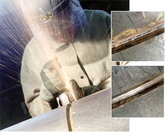
Continuing with our collaboration with TWI, the AWI has bought you a further series of Job Knowledge articles. The following articles are all about typical fabrication defects, their possible causes and suggestions of remedies.
Incomplete root fusion and penetration
The SS Schenectady, an all welded tanker, broke in two whilst lying in dock in 1943. Principal causes of this failure 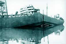 were poor design and bad workmanship
The characteristic features and principal causes of incomplete root fusion and penetration are described. General guidelines on ‘best practice’ are given so welders can minimise the risk of introducing imperfections during fabrication.
Fabrication and service defects and imperfections
As the presence of imperfections in a welded joint may not render the component defective in the sense of being unsuitable for the intended application, the preferred term is imperfection rather than defect. For this reason, production quality for a component is defined in terms of a quality level in which the limits for the imperfections are clearly defined, for example Level B, C or D in accordance with the requirements of BS EN ISO 5817. For the American standards ASME IX and AWS D1.1, the acceptance levels are contained in the standards.
The application code will specify the quality levels which must be achieved for the various joints.
Imperfections can be broadly classified into those produced on fabrication of the component or structure and those formed as result of adverse conditions during service. The principal types of imperfections are:
Fabrication:
- lack of fusion
- lack of or incomplete penetration
- cracks
- porosity
- inclusions
- incorrect weld shape and size
Service:
- brittle fracture
- stress corrosion cracking
- fatigue failure
Welding procedure, joint features and access and welder technique will have a direct effect on fabrication imperfections. Incorrect procedure or poor technique may produce imperfections leading to premature failure in service.
Incomplete root fusion or penetration
Identification
Incomplete root fusion is when the weld fails to fuse one side of the joint in the root. Incomplete root penetration occurs when both sides root region of the joint are unfused. Typical imperfections can arise in the following situations:
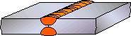
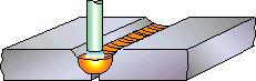
- an excessively thick root face in a butt weld (Fig. 1a)
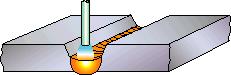
- too small a root gap (Fig. 1b)
- misplaced welds (Fig. 1c)
- failure to remove sufficient metal in cutting back to sound metal in a double sided weld (Fig. 1d)
- incomplete root fusion when using too low an arc energy (heat) input (Fig. 1e)
- too small a bevel angle
a) Excessively thick root face
b) Too small a root gap
c) Misplaced welds
d) Power input too low
e) Arc (heat) input too low
Fig. 1 Causes of incomplete root fusion
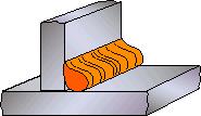
- too large or too small a diameter electrode in MMA welding (Fig 2a and b)
a) Large diameter electrode
b) Small diameter electrode
Fig. 2 Effect of electrode diameter on root fusion and penetration
Causes
These types of imperfection are more likely in consumable electrode processes (MIG, MAG, FCAW, MMA and SAW) where the weld metal is ‘automatically’ deposited as the arc consumes the electrode wire or rod.
The welder has limited control of weld pool penetration independent of depositing weld metal. Thus, the non-consumable electrode TIG process in which the welder controls the amount of filler material deposited independent of penetration is less prone to this type of defect.
In MMA welding, the risk of incomplete root fusion and root penetration can be reduced by using the correct welding parameters and electrode diameter to give adequate arc energy input and satisfactory penetration.
Electrode diameter is also important in that it should be small enough to give adequate access to the root, especially when using a small included vee angle (Fig 2). It is common practice to use either a 2.5mm or 3.25mm diameter electrode for the root run so the welder can manipulate the weld pool and control the degree of penetration.
However, for the fill passes where penetration requirements are less critical, a 4mm or 5mm diameter electrode may be used to achieve higher deposition rates.
In MIG welding, the correct welding parameters for the material thickness, and a short arc length, should give adequate weld bead penetration. Too low a current level for the size of root face will give inadequate weld penetration. Too high a level, causing the welder to move too quickly, will result in the weld pool bridging the root without achieving adequate penetration.
It is also essential that the correct root face size and bevel angles are used and that the joint root gap is set accurately. To prevent the root gap from closing, adequate tacking will be required.
Best practice in prevention
The following techniques can be used to prevent lack of root fusion:
- In TIG welding, do not use too large a root face or too small a root gap and ensure the welding current is sufficient for the weld pool to penetrate fully the root
- In MMA welding, use the correct current level and not too large an electrode diameter for the root run
- In MIG / MAG welding, use a sufficiently high welding current level which is supported by the appropriate arc voltage for the application
- When using a joint configuration with a root gap, make sure it is of adequate width and does not close up during tacking and subsequent welding
- Do not use too low a current level causing the weld pool to bridge the root gap without fully penetrating the root.
Acceptance standards
The limits for lack of or incomplete penetration are specified in BS EN ISO 5817 for the three quality levels.
Lack of or incomplete root penetration is not permitted for Quality Level B (stringent) and Level C (intermediate). However, Level C makes an exception for partial penetration butt welds welded from both sides.
For Quality Level D (moderate) short lack of or incomplete penetration imperfections are permitted.
Incomplete root penetration is not permitted in the manufacture of pressure vessels but is allowable in the manufacture of pipework depending on material and wall thickness.
Remedial actions
If the root cannot be directly inspected, for example using a penetrant or magnetic particle inspection technique, detection is by radiography or ultrasonic inspection.
Remedial action will normally require removal by gouging or grinding to sound metal, followed by re-welding usually in conformity with the original welding procedure.
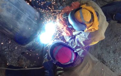
Weld defects/imperfections in welds – lack of sidewall and inter-run fusion
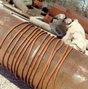
Demagnetising a pipe
This article describes the characteristic features and principal causes of lack of sidewall and inter-run fusion. General guidelines on best practice are given so that welders can minimise the risk of imperfections during fabrication.
Identification
Lack of fusion imperfections can occur when the weld metal fails
- to fuse completely with the sidewall of the joint (Fig. 3)
- to penetrate adequately the previous weld bead (Fig. 4).
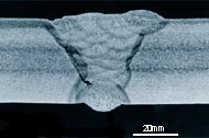
Fig. 3. Lack of side wall fusion
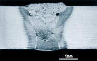
Fig. 4. Lack of inter-run fusion
Causes
The principal causes are too narrow a joint preparation, incorrect welding parameter settings, poor welder technique and magnetic arc blow. Insufficient cleaning of oily or scaled surfaces can also contribute to lack of fusion. These types of imperfection are more likely to happen when access to the joint is restricted.
Joint preparation
Too narrow a joint preparation often causes the arc to be attracted to one of the side walls causing lack of side wall fusion on the other side of the joint or inadequate penetration into the previously deposited weld bead.
Too great an arc length may also increase the risk of preferential melting along one side of the joint and cause shallow penetration. In addition, a narrow joint preparation may prevent adequate access into the joint or encourage flooding the joint with moulting weld metal.
For example, this happens in MMA welding when using a large diameter electrode, or in MIG, MAG and FCAW welding where an allowance has not been made for the diameter of the shielding gas nozzle.
Consideration should also be given to fabrication features that may obstruct the welding torch.
Welding parameters
It is important to use a sufficiently high current for the arc to penetrate into the joint sidewall and previously deposited weld runs. Consequently, too high a welding speed for the welding current will increase the risk of these imperfections.
However, too high a current or too low a welding speed will cause weld pool flooding ahead of the arc resulting in poor or non-uniform penetration.
Welder technique
Poor welder technique such as incorrect angle or manipulation of the electrode/welding gun, will prevent adequate fusion of the joint sidewall. Weaving, especially dwelling at the joint sidewall, will enable the weld pool to wash into the parent metal, greatly improving sidewall fusion. It should be noted that the amount of weaving may be restricted by the welding procedure specification limiting the arc energy input, particularly when welding alloy or high notch toughness steels.
Magnetic arc blow
When welding ferromagnetic steels lack of fusion imperfections can be caused through uncontrolled deflection of the arc, usually termed arc blow. Arc deflection can be caused by distortion of the magnetic field produced by the arc current (Fig. 5), through:
- residual magnetism in the material through using magnets for handling
- earth’s magnetic field, for example in pipeline welding
- position of the current return cable clamp
The effect of welding past the current return cable which is bolted to the centre of the place is shown in Fig. 6.
The interaction of the magnetic field surrounding the arc and that generated by the current flow in the plate to the current return cable is sufficient to deflect the weld bead. Distortion of the arc current magnetic field can be minimised by positioning the current return cable clamp so that welding is always towards or away from the clamp and, in MMA welding, by using AC instead of DC. Often the only effective means is to demagnetise the steel before welding.
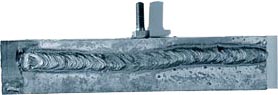
Fig. 5. Interaction of magnetic forces causing arc deflection
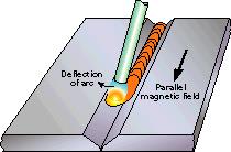
Fig. 6. Weld bead deflection in DC MMA welding caused by welding past the current return connection
Best practice in prevention
The following fabrication techniques can be used to prevent formation of lack of sidewall and inter-run fusion imperfections:
- use a sufficiently wide joint preparation
- select welding parameters (high current level, short arc length, not too high a welding speed) to promote penetration into the joint side wall and previously deposited weld runs without causing flooding
- ensure the electrode/gun angle and manipulation technique will give adequate side wall fusion
- use weaving and dwell to improve side wall fusion providing there are no heat input restrictions
- if arc blow occurs, reposition the current return cable clamp, use AC (in MMA welding) or demagnetise the steel
Acceptance standards
The limits for incomplete fusion imperfections in arc welded joints in steel are specified in BS EN ISO 5817 for the three quality levels (see Table). These types of imperfection are not permitted for Quality Level B (stringent) and C (intermediate). For Quality level D (moderate) they are only permitted providing they are intermittent and not surface breaking.
For arc welded joints in aluminium, long imperfections are not permitted for all three quality levels. However, for quality levels C and D, short imperfections are permitted but the total length of the imperfections is limited depending on the butt weld or the fillet weld throat thickness.
Acceptance limits for specific codes and application standards
| Application | Code/Standard | Acceptance limit |
| Steel | BS EN ISO 5817:2007 | Level B and C not permitted. Level D short imperfections permitted but not surface breaking. |
| Aluminium | BS EN ISO 10042:2005 | Levels B, C, D. Long imperfections not permitted. Levels C and D. Short imperfections permitted. |
| Pressure vessels | BS PD5500:2012+A1: 2012 | Not permitted |
| Storage tanks | BS EN 14015:2004 | Not permitted |
| Pipework | BS2633:1994 | ‘l’ not greater than 15mm (depending on wall thickness) |
| Line pipe | API 1104 (R2010) | ‘l’ not greater than 25mm (less when weld length <300mm) |
Detection and remedial action
If the imperfections are surface breaking, they can be detected using a penetrant or magnetic particle inspection technique. For sub-surface imperfections, detection is by radiography or ultrasonic inspection. Ultrasonic inspection is normally more effective than radiography in detecting lack of inter-run fusion imperfections.
Remedial action will normally require their removal by localised gouging, or grinding, followed by re-welding as specified in the agreed welding procedure.
If lack of fusion is a persistent problem, and is not caused by magnetic arc blow, the welding procedures should be amended or the welders retrained.
Defects/imperfections in welds – porosity
The characteristic features and principal causes of porosity imperfections are described.
Best practice guidelines are given so welders can minimise porosity risk during fabrication.
Identification
Porosity is the presence of cavities in the weld metal caused by the freezing in of gas released from the weld pool as it solidifies. The porosity can take several forms:
- distributed
- surface breaking pores
- wormhole
- crater pipes
Cause and prevention
Distributed porosity and surface pores
Distributed porosity (Fig. 7) is normally found as fine pores throughout the weld bead. Surface breaking pores (Fig. 8) usually indicate a large amount of distributed porosity.
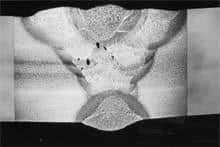
Fig. 7. Uniformly distributed porosity
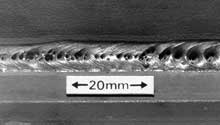
Fig. 8. Surface breaking pores (T fillet weld in primed plate)
Cause
Porosity is caused by the absorption of nitrogen, oxygen and hydrogen in the molten weld pool which is then released on solidification to become trapped in the weld metal.
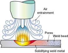
Nitrogen and oxygen absorption in the weld pool usually originates from poor gas shielding. As little as 1% air entrainment in the shielding gas will cause distributed porosity and greater than 1.5% results in gross surface breaking pores.
Leaks in the gas line, too high a gas flow rate, draughts and excessive turbulence in the weld pool are frequent causes of porosity.
Hydrogen can originate from a number of sources including moisture from inadequately dried electrodes, fluxes or the workpiece surface. Grease and oil on the surface of the workpiece or filler wire are also common sources of hydrogen.
Surface coatings like primer paints and surface treatments such as zinc coatings, may generate copious amounts of fume during welding. The risk of trapping the evolved gas will be greater in T joints than butt joints especially when fillet welding on both sides (see Fig ) Special mention should be made of the so-called weldable (low zinc) primers.
It should not be necessary to remove the primers but if the primer thickness exceeds the manufacturer’s recommendation, porosity is likely to result especially when using welding processes other than MMA.
Prevention
The gas source should be identified and removed as follows:
Air entrainment
- seal any air leak
- avoid weld pool turbulence
- use filler with adequate level of deoxidants
- reduce excessively high gas flow
- avoid draughts
Hydrogen
- dry the electrode and flux
- clean and degrease the workpiece surface
Surface coatings
- clean the joint edges immediately before welding
- check that the weldable primer is below the recommended maximum thickness
Elongated pores or wormholes
Wormholes
Characteristically, wormholes are elongated pores (Fig. 9) which produce a herring bone appearance on the radiograph.
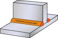
Fig. 9 Elongated pores which producing a herring bone appearance
Cause
Wormholes are indicative of a large amount of gas being formed which is then trapped in the solidifying weld metal. Excessive gas will be formed from gross surface contamination or very thick paint or primer coatings. Entrapment is more likely in crevices such as the gap beneath the vertical member of a horizontal-vertical, T joint which is fillet welded on both sides.
When welding T joints in primed plates it is essential that the coating thickness on the edge of the vertical member is not above the manufacturer’s recommended maximum, typically 20µm, through over-spraying.
Prevention
Eliminating the gas and cavities prevents wormholes.
Gas generation
- clean the workpiece surfaces at and adjacent to the location where the weld will be made
- remove any surface contamination, in particular oil, grease, rust and residue from NDT operations
- remove any surface coatings from the joint area to expose bright material
- check the primer thickness is below the manufacturer’s maximum
Joint geometry
- avoid a joint geometry which creates a cavity
Crater pipe
A crater pipe forms during the final solidification of the weld pool and is often associated with some gas porosity.
Cause
This imperfection results from shrinkage on weld pool solidification. Consequently, conditions which exaggerate the liquid to solid volume change will promote its formation.
Extinguishing the welding arc will result in the rapid solidification of the weld pool.
In TIG welding, autogenous techniques, or stopping the welding wire entering the weld pool before extinguishing the welding arc, will effect crater formation and may promote the pipe imperfection.
Prevention
Crater pipe imperfection can be prevented by controlling the rate at which the welding arc is extinguished or by welder technique manipulating the welding arc and welding wire
Removal of stop
- use run-off tag to enable the welding arc to be extinguished outside the welded joint
- grind out the weld run stop crater before continuing with the next electrode or depositing the subsequent weld run
Welder technique
- progressively reduce the welding current to reduce the weld pool size (use slope-down or crater fill functions)
- add filler (TIG) to compensate for the weld pool shrinkage
Porosity susceptibility of materials
Gases likely to cause porosity in the commonly used range of materials are listed in the Table.
Principal gases causing porosity and recommended cleaning methods
| Material | Gas | Cleaning |
| C-Mn steel | Hydrogen, Nitrogen and Oxygen | Grind to remove scale coatings |
| Stainless steel | Hydrogen | Degrease + wire brush + degrease |
| Aluminium and alloys | Hydrogen | Chemical clean + wire brush + degrease + scrape |
| Copper and alloys | Hydrogen, Nitrogen | Degrease + wire brush + degrease |
| Nickel and alloys | Nitrogen | Degrease + wire brush + degrease |
Detection and remedial action
If the imperfections are surface breaking, they can be detected using a penetrant or magnetic particle inspection technique. For sub surface imperfections, detection is by radiography or ultrasonic inspection. Radiography is normally more effective in detecting and characterising porosity imperfections. However, detection of small pores is difficult especially in thick sections.
Remedial action normally needs removal by localised gouging or grinding but if the porosity is widespread, the entire weld should be removed. The joint should be re-prepared and re-welded as specified in the agreed welding procedure.
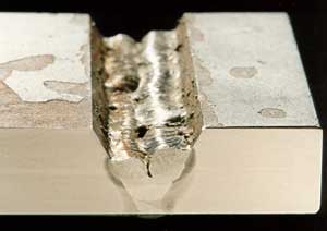
Defects/imperfections in welds – slag inclusions
Prevention of slag inclusions by grinding between runs
The characteristic features and principal causes of slag imperfections are described.
Identification
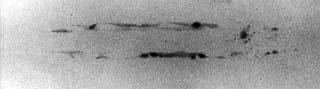
Fig. 10. Radiograph of a butt weld showing two slag lines in the weld root
Slag is normally seen as elongated lines either continuous or discontinuous along the length of the weld. This is readily identified in a radiograph, Fig 10. Slag inclusions are usually associated with the flux processes, i.e. MMA, FCA and submerged arc, but they can also occur in MIG welding.
Causes
As slag is the residue of the flux coating in MMA welding, it is principally a de-oxidation product from the reaction between the flux, air and surface oxide. The slag becomes trapped in the weld when two adjacent weld beads are deposited with inadequate overlap and a void is formed.
When the next layer is deposited, the entrapped slag is not melted out. Slag may also become entrapped in cavities in multi-pass welds through excessive undercut in the weld toe or the uneven surface profile of the preceding weld runs, Fig 11.
As they both have an effect on the ease of slag removal, the risk of slag imperfections is influenced by
- Type of flux coating
- Welder technique
The type and configuration of the joint, welding position and access restrictions all have an influence on the risk of slag imperfections.
a) Poor (convex) weld bead profile resulted in pockets of slag being trapped between the weld runs
b) Smooth weld bead profile allows the slag to be readily removed between runs
Figures. 11 a & b. The influence of welder technique on the risk of slag inclusions when welding with a basic MMA (E7018) electrode
Type of flux coating
One of the main functions of the flux coating in welding is to produce a slag which will flow freely over the surface of the weld pool to protect it from oxidation. As the slag affects the handling characteristics of the MMA electrode, its surface tension and freezing rate can be equally important properties.
For welding in the flat and horizontal/vertical positions, a relatively viscous slag is preferred as it will produce a smooth weld bead profile, is less likely to be trapped and, on solidifying, is normally more easily removed.
For vertical welding, the slag must be more fluid to flow out to the weld pool surface but have a higher surface tension to provide support to the weld pool and be fast freezing.
The composition of the flux coating also plays an important role in the risk of slag inclusions through its effect on the weld bead shape and the ease with which the slag can be removed.
A weld pool with low oxygen content will have a high surface tension producing a convex weld bead with poor parent metal wetting. Thus, an oxidising flux, containing for example iron oxide, produces a low surface tension weld pool with a more concave weld bead profile, and promotes wetting into the parent metal.
High silicate flux produces a glass-like slag, often self-detaching.
Fluxes with a lime content produce an adherent slag which is difficult to remove.
The ease of slag removal for the principal flux types are:
- Rutile or acid fluxes – large amounts of titanium oxide (rutile) with some silicates. The oxygen level of the weld pool is high enough to give flat or slightly convex weld bead. The fluidity of the slag is determined by the calcium fluoride content.
- Fluoride-free coatings designed for welding in the flat position produce smooth bead profiles and an easily removed slag. The more fluid fluoride slag designed for positional welding is less easily removed.
- Basic fluxes – the high proportion of calcium carbonate (limestone) and calcium fluoride (fluospar) in the flux reduces the oxygen content of the weld pool and therefore its surface tension.
- The slag is more fluid than that produced with the rutile coating. Fast freezing also assists welding in the vertical and overhead positions but the slag coating is more difficult to remove.
Consequently, the risk of slag inclusions is significantly greater with basic fluxes due to the inherent convex weld bead profile and the difficulty in removing the slag from the weld toes especially in multi-pass welds.
Welder technique
Welding technique has an important role to play in preventing slag inclusions. Electrode manipulation should ensure adequate shape and degree of overlap of the weld beads to avoid forming pockets which can trap the slag.
Thus, the correct size of electrode for the joint preparation, the correct angle to the workpiece for good penetration and a smooth weld bead profile are all essential to prevent slag entrainment.
In multi-pass vertical welding, especially with basic electrodes, care must be taken to fuse out any remaining minor slag pockets and minimise undercut. When using a weave, a slight dwell at the extreme edges of the weave will assist sidewall fusion and produce a flatter weld bead profile. Too high a current together with a high welding speed will also cause sidewall undercutting which makes slag removal difficult.
It is crucial to remove all slag before depositing the next run. This can be done between runs by grinding, light chipping or wire brushing. Cleaning tools must be identified for different materials eg steels or stainless steels, and segregated. When welding with difficult electrodes, in narrow vee butt joints or when the slag is trapped through undercutting, it may be necessary to grind the surface of the weld between layers to ensure complete slag removal.
Best practice
The following techniques can be used to prevent slag inclusions:
- Use welding techniques to produce smooth weld beads and adequate inter-run fusion to avoid forming pockets to trap the slag
- Use the correct current and travel speed to avoid undercutting the sidewall which will make the slag difficult to remove
- Remove slag between runs paying particular attention to removing any slag trapped in crevices
- Use grinding when welding difficult butt joints otherwise wire brushing or light chipping may be sufficient to remove the slag.
Copyright © TWI Ltd 2014
The content of this article was correct at the time of publication. For more information visit www.twi-global.com