ESAB KNOWLEDGE CENTER
An Introduction to Welding Inspection
Many characteristics of a weld can be evaluated during welding inspection, some relating to the welds size, and others relating to the presence of weld discontinuities. The size of a weld can be extremely important, as it can often relate directly to the weld’s strength and associated performance, undersized weld’s may not withstand stresses applied during service. Weld discontinuities can also be important. These are imperfections within or adjacent to the weld, which may or may not, dependent on their size and/or location, prevent the weld from meeting its intended performance. Typically these discontinuities, when of unacceptable size or location, are referred to as welding defects, and can sometimes cause premature weld failure through reduction of the weld strength or through producing stress concentrations within the welded component.
The inspection of welds can be conducted for a number of reasons. Perhaps the most fundamental reason is to determine whether the weld is of suitable quality for its intended application. In order to evaluate a weld’s quality, we must first have some form of measuring block with which to compare its characteristics. It is impractical to attempt to evaluate a weld’s quality without some form of specified acceptance criteria.
Weld quality acceptance criteria can originate from a number of sources. The welding fabrication drawing/blue print will typically provide weld sizes and possibly other welding dimensional information, such as length and location of welds.
These dimensional requirements will usually have been established through design calculations or taken from proven designs that are known to meet the performance requirements of the welded connection.
Acceptable and unacceptable levels or amounts of weld discontinuities for welding inspection are usually obtained from welding codes and standards. Welding codes and standards have been developed for many types of welding fabrication applications. It is important to choose a welding standard that is intended for use within the particular industry or application in which you are involved.
Welding inspection can often require a wide variety of knowledge on the part of the welding inspector: the understanding of welding drawings, welding symbols, weld joint design, welding procedures, code and standard requirements and inspection and testing techniques, to name a few. For this reason many welding codes and standards require that the welding inspector be formally qualified or have the necessary knowledge and experience to conduct the inspection services. There are a number of welding inspection training courses available and a number of welding inspector certification programs internationally. The most popular program used in the UK is administered by CSWIP. CSWIP certification schemes are UKAS-accredited to ISO/IEC 17024, the international standard for personnel certification.
Certification as a welding inspector: will typically require demonstration of an individual’s knowledge of welding inspection through passing examination. In order to further appreciate the extent of welding inspection we will need to examine specific areas of inspection techniques and welding inspection applications. I have chosen the following topics to provide this welding inspection overview:
- Inspection and Testing for Welding Procedure Qualification – Types of inspection used for these requirements and how they can be an essential part of the overall welding quality system.
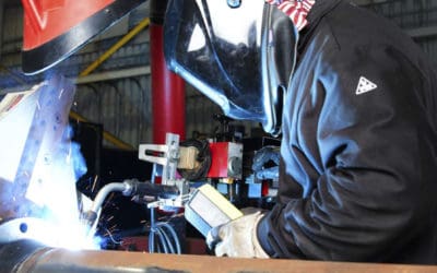
- Visual Inspection – Often the easiest, least expensive, and probably, if performed correctly, the most effective method of welding inspection for many applications.
- Surface Crack Detection – Methods such as Liquid Penetrant Inspection and Magnetic Particle Inspection – How they are used and what they will find.
- Radiographic and Ultrasonic Weld Inspection – Methods known as Non Destructive Testing (NDT) and used typically to examine the internal structure of the weld in order to establish the weld’s integrity without destroying the welded component.
- Destructive Weld Testing – Methods used to establish weld integrity or performance, typically through sectioning and/or breaking the welded component and evaluating various mechanical and or physical characteristics.
One of the main ingredients of a successful welding quality system is the establishment, introduction and control of a sound welding inspection program. Only after the full evaluation of the weld quality requirements/acceptance criteria, the full appreciation of the inspection and testing methods to be used, and the availability of suitably qualified and/or experienced welding inspectors can such a program be established.
ESAB Q & A
Q: Can I weld aluminium to steel with the GMAW or GTAW welding process?
A: While aluminium can be joined to most other metals relatively easily by adhesive bonding or mechanical fastening, special techniques are required if it is to be arc welded to other metals such as steel. Very brittle intermetallic compounds are formed when metals such as steel, copper, magnesium or titanium are directly arc welded to aluminium.
To avoid these brittle compounds, some special techniques have been developed to isolate the other metal from the molten aluminium during the arc welding process.
The two most common methods of facilitating arc welding of aluminium to steel are bimetallic transition inserts and coating the dissimilar material prior to welding.
Bimetallic Transition Inserts
Bimetallic transition materials are available commercially in combinations of aluminium to such other materials as steel, stainless steel and copper. These inserts are best described as sections of material that are comprised of one part aluminium with another material already bonded to the aluminium. The method used for bonding these dissimilar materials together, and thus forming the bimetallic transition, are usually rolling, explosion welding, friction welding, flash welding or hot pressure welding, and not arc welding.
The arc welding of these steel aluminium transition inserts can be performed by the normal arc welding methods such as GMAW or GTAW. One side of the insert is welded steel-to-steel and the other aluminium-to-aluminium.
Care should be taken to avoid overheating the inserts during welding, which may cause growth of brittle intermetallic compounds at the steel-aluminium interface of the transition insert. It is good practice to perform the aluminium-to-aluminium weld first. In this way, we can provide a larger heat sink when the steel-to-steel welding is performed and help prevent the steel aluminium interface from overheating.
The bimetallic transition insert is a popular method of joining aluminium to steel and is often used for producing welded connections of excellent quality within structural applications. Such applications as attaching aluminium deckhouses to steel decks on ships, for tube sheets in heat exchangers that have aluminium tubing with steel or stainless steel tube sheets, and for producing arc welded joints between aluminium and steel pipe lines.
Coating the Dissimilar Material Prior to Welding
A coating can be applied to steel to facilitate its arc welding to aluminium. One method is to coat the steel with aluminium. This is sometimes achieved by dip coating (hot dip aluminising), or brazing the aluminium to the surface of the steel. Once coated, the steel member can be arc welded to the aluminium member, if care is taken to prevent the arc from impinging on the steel.
A technique must be used during welding to direct the arc onto the aluminium member and allow the molten aluminium from the weld pool to flow onto the aluminium coated steel.
Another method of joining aluminium to steel involves coating the steel surface with silver solder. The joint is then welded using aluminium filler alloy, taking care not to burn through the barrier layer of silver solder. Neither of these coating type joint methods are typically depended upon for full mechanical strength and are usually used for sealing purposes only.
Coreweld 46 LS
Coreweld 46 LS is a new generation metal cored wire based on ESAB’s revolutionary cored wire surface technology.
It has been developed for the welding of thin-plate with a minimum thickness of 1.0 mm and provides fabricators with a substantially faster and higher quality welding solution to solid MAG wire.
The absence or very low levels of silica on the weld surface and minimal spatter result in reduced post weld cleaning before coating/painting. Coreweld 46 LS is a unique product that markedly lowers the welding costs for mechanised and robotic fabrication.
The many advantages relative to solid wire are associated with the extremely wide spray arc parameter envelope that starts as low as 160A. With solid wire spray arc starts at around 200A for diameter 1.0 mm and 230A for diameter 1.2 mm.
These features are valid for the standard shielding gas M21 (Ar + 15-25% CO2), although optimal results are obtained in 92% Ar + 8% CO2 mixtures. Switching from solid wire to Coreweld 46 LS will in most cases, require no change in the positioning of the welding gun so the conversion time is limited to the optimisation of welding parameters.
Coreweld 89
Coreweld 89 is a new metal cored wire for the welding of high strength steel with a minimum yield strength of 900 MPa.
These steels are increasingly used to create lighter, higher performance structures with good overall cost effectiveness, together with lower environmental impacts.
When welding high strength steel, it is very important to use low diffusible hydrogen welding consumables in order to avoid hydrogen induced cold cracking. Coreweld 89 falls into this area, meeting the strict AWS H4 and EN ISO H5 requirements. Coreweld 89 provides excellent sub-zero toughness down to -40ºC and low diffusible hydrogen levels, using shielding gas in the range Ar/5-25% CO2(EN ISO 14175 M20 and M21). Coreweld 89 has all beneficial features attributed to ESAB metal cored wires including a smooth arc transfer which produces minimal spatter and silica level on the weld metal surface.
With the resulting wide arc the risk of lack of fusion defects is significantly reduced which can be a problem when using the GMAW process. Typical applications are found in the manual, mechanized or robotic welding of components such as: Crane arms and other lifting equipment, booms for forest machinery, chassis and bodywork of commercial vehicles, load support and fastening equipment, load handling equipment, feeding and unloading hoppers and containers.