
Mechanical testing – Tensile testing, Part 1
Mechanical testing is carried out to produce data that may be used for design purposes or as part of a material joining procedure or operator acceptance scheme. The most important function may be that of providing design data since it is essential that the limiting values that a structure can withstand without failure are known.
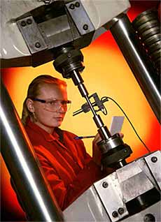
Fig.1. Typical tensile testing machine
Inadequate control of the material properties by the supplier, or incompetent joining procedures and operatives are, however, equally crucial to the supply of a product that is safe in use. An example of this dual role of mechanical testing is the tensile test that may be used either to determine the yield strength of a steel for use in design calculations or to ensure that the steel complies with a material specification’s strength requirements.
Mechanical tests may also be divided into quantitative or qualitative tests. A quantitative test is one that provides data that will be used for design purposes, a qualitative test where the results will be used for making comparisons – hardness or Charpy-V tests – for example as a ‘go/no go test’ such as the bend test.
Mechanical property data are obtained from a relatively small number of standard tests and these will be covered over the next several articles. These will include tensile and toughness tests, the tests used for welding procedure and welder approval and those used for the determination of in-service properties.
Tensile testing
As mentioned earlier the tensile test is used to provide information that will be used in design calculations or to demonstrate that a material complies with the requirements of the appropriate specification – it may therefore be either a quantitative or a qualitative test.
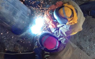
The test is made by gripping the ends of a suitably prepared standardised test piece in a tensile test machine and then applying a continually increasing uni-axial load until such time as failure occurs. Test pieces are standardised in order that results are reproducible and comparable as shown in Fig 2.
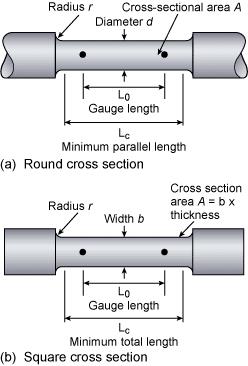
Fig.2. Standard shape tensile specimens
Specimens are said to be proportional when the gauge length, L0, is related to the original cross sectional area, A0, expressed as L0=k√A0. The constant k is 5.65 in EN specifications and 5 in the ASME codes. These give gauge lengths of approximately 5x specimen diameter and 4x specimen diameter respectively – whilst this difference may not be technically significant it is important when claiming compliance with specifications.
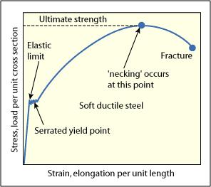
Fig.3. Stress/strain curve
Both the load (stress) and the test piece extension (strain) are measured and from this data an engineering stress/strain curve is constructed, Fig.3. From this curve we can determine:
b) the yield point(YP), the stress at which deformation changes from elastic to plastic behaviour i.e. below the yield point unloading the specimen means that it returns to its original length, above the yield point permanent plastic deformation has occurred, YP or σy= Pyp /A0 where Pyp = load at the yield point. In EN specifications this parameter is also identified as ‘Re‘
c) By reassembling the broken specimen we can also measure the percentage elongation, El% how much the test piece had stretched at failure where El% = (Lf– L0/Lo) x100 where Lf = gauge length at fracture and L0 = original gauge length. In EN specifications this parameter is also identified as ‘A’ (Fig.4a).
d) The percentage reduction of area, how much the specimen has necked or reduced in diameter at the point of failure where R of A% = (A0– Af/A0) x 100 where Af= cross sectional area at site of the fracture. In EN specifications this parameter is also identified as ‘Z’, (4b).
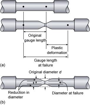
Fig.4: a) Calculation of percentage elongation, b) Calculation of percentage reduction of area
(a) and (b) are measures of the strength of the material, (c) and (d) indicate the ductility or ability of the material to deform without fracture.
The slope of the elastic portion of the curve, essentially a straight line, will give Young’s Modulus of Elasticity, a measure of how much a structure will elastically deform when loaded.
A low modulus means that a structure will be flexible, a high modulus a structure that will be stiff and inflexible.
To produce the most accurate stress/strain curve an extensometer should be attached to the specimen to measure the elongation of the gauge length. A less accurate method is to measure the movement of the cross-head of the tensile machine.
The stress strain curve in Fig.3 shows a material that has a well pronounced yield point but only annealed carbon steel exhibits this sort of behaviour. Metals that are strengthened by alloying, by heat treatment or by cold working do not have a pronounced yield and some other method must be found to determine the ‘yield point’.
This is done by measuring the proof stress (offset yield strength in American terminology), the stress required to produce a small specified amount of plastic deformation in the test piece.
The proof stress is measured by drawing a line parallel to the elastic portion of the stress/strain curve at a specified strain, this strain being a percentage of the original gauge length, hence 0.2% proof, 1% proof (see Fig.5).
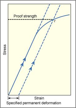
Fig.5. Determination of proof (offset yield) strength
For example, 0.2% proof strength would be measured using 0.2mm of permanent deformation in a specimen with a gauge length of 100mm. Proof strength is therefore not a fixed material characteristic, such as the yield point, but will depend upon how much plastic deformation is specified. It is essential therefore when considering proof strengths that the percentage figure is always quoted. Most steel specifications use 0.2% deformation, RP0.2 in the EN specifications.
Some materials such as annealed copper, grey iron and plastics do not have a straight line elastic portion on the stress/strain curve. In this case the usual practice, analogous to the method of determining proof strength, is to define the ‘yield strength’ as the stress to produce a specified amount of permanent deformation.
Part 2 of this series on mechanical testing will cover welding procedure approval tensile testing.
Bend testing
The bend test is a simple and inexpensive qualitative test that can be used to evaluate both the ductility and soundness of a material. It is often used as a quality control test for butt-welded joints, having the advantage of simplicity of both test piece and equipment.
No expensive test equipment is needed, test specimens are easily prepared and the test can, if required, be carried out on the shop floor as a quality control test to ensure consistency in production.
The bend test uses a coupon that is bent in three point bending to a specified angle.
The outside of the bend is extensively plastically deformed so that any defects in, or embrittlement of, the material will be revealed by the premature failure of the coupon.
The bend test may be free formed or guided.
The guided bend test is where the coupon is wrapped around a former of a specified diameter and is the type of test specified in the welding procedure and welder qualification specifications. For example, it may be a requirement in ASME IX, ISO 9606 and ISO 15614 Part 1.
As the guided bend test is the only form of bend test specified in welding qualification specifications it is the only one that will be dealt with in this article.
Typical bend test jigs are illustrated in Fig.1 (a) and 1(b).
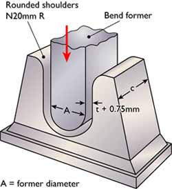
Fig.1 (a) shows a guided bend test jig that uses a male and a female former, the commonest form of equipment
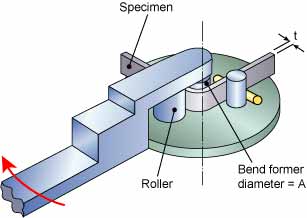
Fig.1 (b) shows a wrap-around guided bend test machine that works on the same principles as a plumber’s pipe bender
The strain applied to the specimen depends on the diameter of the former around which the coupon is bent and this is related to the thickness of the coupon ‘t’, normally expressed as a multiple of ‘t’ e.g. 3t, 4t etc.
The former diameter is specified in the test standard and varies with the strength and ductility of the material – the bend former diameter for a low ductility material such as a fully hard aluminium alloy may be as large as 8t. An annealed low carbon steel on the other hand may require a former diameter of only 3t. The angle of bend may be 90°, 120° or 180° depending on the specification requirements.
On completion of the test the coupon is examined for defects that may have opened up on the tension face. Most specifications regard a defect over 3mm in length as being cause for rejection.
For butt weld procedure and welder qualification testing the bend coupons may be oriented transverse or parallel to the welding direction.
Below approximately 12mm material thickness transverse specimens are usually tested with the root or face of the weld in tension. Material over 12mm thick is normally tested using the side bend test that tests the full section thickness, Fig.2.
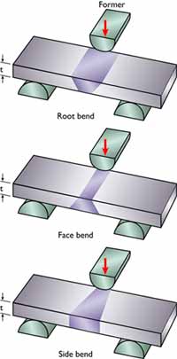
Fig.2 Material over 12mm thick is normally tested using the side bend test that tests the full section thickness
Where the material thickness is too great to permit the full section to be bent the specifications allow a number of narrower specimens to be taken provided that the full material thickness is tested. Conventionally, most welding specifications require two root and two face bend coupons or four side bends to be taken from each butt welded test piece.
The transverse face bend specimen will reveal any defects on the face such as excessive undercut or lack of sidewall fusion close to the cap. The transverse root bend is also excellent at revealing lack of root fusion or penetration. The transverse side bend tests the full weld thickness and is particularly good at revealing lack of side-wall fusion and lack of root fusion in double-V butt joints. This specimen orientation is also useful for testing weld cladding where any brittle regions close to the fusion line are readily revealed.
Longitudinal bend specimens are machined to include the full weld width, both HAZs and a portion of each parent metal. They may be bent with the face, root or side in tension and are used where there is a difference in mechanical strength between the two parent metals or the parent metal and the weld. The test will readily reveal any transverse defects but it is less good at revealing longitudinally oriented defects such as lack of fusion or penetration.
Whilst the bend test is simple and straightforward to perform there are some features that may result in the test being invalid.
In cutting the coupon from the test weld the effects of the cutting must not be allowed to affect the result. Thus it is necessary to remove any HAZ from flame cutting or work hardened metal if the sample is sheared.
It is normal to machine or grind flat the face and root of a weld bend test coupon to reduce the stress raising effect that these would have. Sharp corners can cause premature failure and should be rounded off to a maximum radius of 3mm.
The edges of transverse bend coupons from small diameter tubes will experience very high tensile stresses when the ID is in tension and this can result in tearing at the specimen edges.
Weld joints with non-uniform properties such as dissimilar metal joints or where the weld and parent metal strengths are substantially different can result in ‘peaking’ of the bend 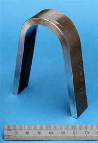 coupon.
This is when most of the deformation takes place in the weaker of the two materials which therefore experiences excessive localised deformation that may result in premature failure.
A dissimilar metal joint where one of the parent metals is very high strength is a good example of where this may occur and similar peaking can be seen in fully hard welded aluminium alloy joints.
In these instances the roller bend test illustrated in Fig.1 (b) is the best method of performing a bend test as each component of the coupon is strained by a similar amount and peaking is to a great extent eliminated.
Related Specifications
| BS EN 910 | Destructive Tests on Welds in Metallic Materials – Bend Tests |
| ASME IX | Welding and Brazing Qualifications |
| ASTM E190-92 | Guided bend Test for Ductility of Welds |
This article was written by Gene Mathers.
Copyright © TWI Ltd 2014
The content of this article was correct at the time of publication. For more information visit www.twi-global.com