
Job Knowledge – Radiography
Radiography is one of the best know processes for reliably detecting buried imperfections – a so-called volumetric detection method. The first such method to be used in manufacturing to determine the quality of fabricated components is radiography. X-rays generated from a cathode ray tube were discovered in the late 1890’s, soon followed by the discovery of gamma radiation from radioactive isotopes.
The ability of this radiation to penetrate both living and inert objects with the amount of transmitted radiation depending on the density, thickness, and atomic number of the object was eventually understood. The transmitted radiation was found to produce images on photographic film and these findings resulted in the development of industrial radiography as illustrated in Fig. 1.
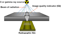
Fig. 1. Principles of radiography
X-radiation is produced from a vacuum tube – this contains a cathode which produces a beam of electrons when an electric current is passed, the higher the voltage the more intense is the stream of electrons and the deeper the penetration – see Table 1.
Industrial X-ray tubes use voltages between 20kV and some 450kV but up to 30MV in linear accelerator and betatron equipment.
The stream of electrons impacts an anode, some 1% of the energy being emitted as a beam of X-rays, the remainder being released as heat, requiring the anode to be cooled, often with water or oil. A schematic of an X-ray tube is shown as Fig. 2. The anode can be designed to provide a beam as illustrated in Fig. 2 or a 360O panoramic beam, typically used for pipe butt weld inspection with the X-ray source inside the pipe.
| kV | Maximum Thickness (mm) | |
| Steel | Aluminium | |
| 50 | 1 | 12 |
| 100 | 20 | 60 |
| 150 | 30 | 80 |
| 200 | 50 | 100 |
| 300 | 80 | 150 |
| 400 | 100 | 200 |
| 2000(2MV) | 200 | 500 |
| 25000(25MV) | 500 | 1400 |
Table 1 Applied kV and maximum thickness
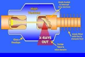
Fig. 2 Schematic of an X-ray tube
Gamma radiation is naturally occurring and is produced by the decay of a radioactive isotope which, when it decays, emits three types of radiation, alpha, beta and gamma.
Alpha and beta radiation are short range and very easily absorbed – gamma radiation, however, is very energetic, typically over 100keV, and can easily pass through a metal, the thickness that can be penetrated depending on the type and size of isotope.
The isotopes are stored in shielded containers from which they can be wound to expose the isotope, as shown in Fig 3.
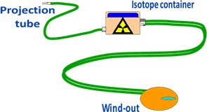
Fig 3. Typical arrangement of gamma ray NDE equipment
Each isotope has a “half -life”- a length of time by which half (50%) of the radioactive isotope has decayed into a stable element – two half-lives means the source has only 25% of its original strength, three half-lives 12.5%. As the source decays and becomes less energetic the length of the exposure time must be increased to achieve the same density of image on the radiographic film. There is thus a point at which use of the gamma ray source is discontinued and replaced with a fresh isotope. In addition, because the gamma radiation emitted by an isotope cannot be varied in quality there is a range of material thickness for which each source will give acceptable results. The commonest isotope in regular use is iridium192 with cobalt60 being used for very thick components.
| Isotope | Half Life | Typical Thickness Range – steel (mm) |
| Iridium 192 | 74 days | 10 – 50 |
| Cobalt 60 | 5.26 years | 25 – 200 |
| Ytterbium 169 | 32 days | < 10 |
| Thulium 170 | 128 days | < 10 |
| Selenium 75 | 119 days | 5 – 20 |
| Caesium 137 | 30 years | 20 – 80 |
Table 2 Half-life and typical thickness range of industrial isotopes.
The film is a fine grained photographic film with a coating of a light sensitive emulsion on both sides which is loaded in a darkroom into a flexible cassette.
The cassette contains an intensifying screen, a card mounted thin lead foil, 0.05 mm to 0.5mm thick, held in close contact with the film. This screen absorbs stray radiation and emits electrons that enable the exposure time to be substantially reduced without affecting the radiographic quality.
The quality of a radiograph is assessed using three factors – density, contrast and definition or sharpness of the image. Most specifications require film densities in the range 1.8 to 2.5 (film density = 1, 1/10th of light is transmitted: film density = 2, 1/100th of light is transmitted). The density of the film can be measured using a densitometer; films outside of the specified range of density would be rejected. The density is affected by the exposure time and metal thickness – this can make the radiography of components with dissimilar thicknesses problematic – thin sections being over-exposed, thick sections under-exposed.
The contrast is determined by the differences in absorption between the metal and the defect and by the type of film used. The speed of the film in particular affects the contrast of the image. Most weld defects are less absorbing than the surrounding metal – slag, porosity, lack of fusion or penetration etc. therefore appear dark against a lighter background.
The only weld defects that are more absorbing than the parent metal are tungsten inclusions that appear as bright white specks on the film.
Sharpness of the image is a function of a number of factors, a radiograph with poor sharpness being somewhat similar to an out-of-focus photograph with fine details being blurred or not visible.
Film with a very fine grain size is preferred for high quality radiography, being capable of resolving fine details. There is a geometric un-sharpness caused by the size of the radiation source, known as the “focal spot”.
A large diameter source will cause a penumbra which means that the edges of an image become blurred as shown in Fig. 4.
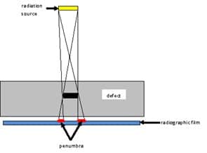
Fig 4. Formation of a penumbra
The further away from the item being radiographed than the less obvious is this effect – unfortunately the further away the source is from the object then the longer is the exposure time – twice the distance quadruples the time. To minimise the penumbra and increase sharpness the source should be the smallest diameter possible; the film should be as close to the back of the object as possible; the source should be as far from the object as possible, bearing in mind the lengthening of exposure time; fine grained film should be used.
Additional un-sharpness is caused by the release of electrons within the film emulsion that darken the adjacent area.
To ensure that radiographs are of an acceptable quality with respect to image sharpness, contrast etc. it is a requirement that an image quality indicator (IQI) is used as can be seen in Fig. 5.
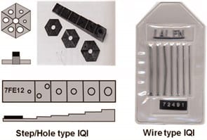
Fig. 5. Image Quality Indicators
The quality of a radiograph is assessed using three factors: density, contrast and definition or sharpness of the image. Density and contrast have already been covered but there also has to be some method by which the sensitivity (the ability to reveal imperfections) can be measured. To do this IQI’s, are used
The wire type is the most frequently used IQI in radiography-by-film. The design of the IQI is given in EN ISO 19232 Part 1 or ASTM E747. Both specifications list a series of IQIs containing six or seven wires of increasing diameter, from 1-8mm, from 10-50mm in length and in a range of metals – iron, nickel, aluminium, magnesium, copper and titanium. The wires are mounted side by side in a flexible plastic sheath which also carries appropriate identification, generally lead letters that will be clearly seen on the radiograph.
The IQI is selected with respect to the metal type and the component thickness; the thicker the component the thicker the IQI’s wires.
The IQI carries an identification and serial number so that it can be confirmed at a later stage that the correct IQI has been used.
Ideally the IQI is placed on the source side of the component and, in the case of a weld, transversely across the joint although this is not always possible when radiographing pipe and tube butt welds. The sensitivity is taken as the smallest diameter wire that can be seen divided by the component thickness, expressed as a percentage.
Most application codes specify a sensitivity of between 2-4%; this is a maximum, the smaller the figure the greater the sensitivity of the radiograph. Alternatively an actual wire diameter that must be visible is specified.
The step hole IQI is used less frequently. It is a stepped wedge with a hole drilled in each step, the hole diameter matching the thickness of the step. As with the wire IQI, the material and dimensions of the step wedge are selected to match the application.
The diameter of the smallest hole visible on the radiograph determines the sensitivity, this being calculated as hole diameter divided by component thickness expressed as a percentage.
The sensitivity measured by the use of a wire IQI is not the same as the sensitivity using a step wedge IQI.
As with any film, the method of processing will affect the quality of the image. Care must be taken to ensure that there is no light contamination, the processing chemicals are at the correct concentrations and temperatures and that drying the film does not leave marks and stains that would leave spurious indications and would make accurate interpretation difficult.
Interpretation of the radiographs must be undertaken by trained and experienced radiographers. In addition to being fully conversant with radiographic techniques such individuals should also have a comprehensive knowledge of welding processes, joint design and the various imperfections that may occur.
Many application specifications require such individuals to be independently certified to a suitable certification scheme.
Viewing should be carried out in a darkened room, allowing a period of time for the viewer’s eyes to be accustomed to the conditions. The luminance of the viewing screen will need to vary with the density of the radiograph – there is generally a rheostat control (a dimmer switch) on the viewer to enable the luminance to be varied. The light itself should be white and diffuse and there should be as little light as possible leaking around the edges of the radiograph.
Radiography of flat plates and cylinders large enough to permit entry for placement of the film is a relatively simple operation, as shown in Fig. 1 of the previous article. Lead numbers are placed at fixed intervals along the plate adjacent to the weld or around the circumference of a pipe to enable the position of any imperfections to be accurately located. The weld also carries a unique identification number reproduced on the radiograph by the use of lead figures placed adjacent to the weld.
Radiography of pipes, however, where access to the bore to place the film is not possible presents some problems and terms such as SWSI and DWSI are used as shorthand to identify the various techniques that may be used.
Single wall, single image (SWSI) is a technique whereby the radiographic source is placed inside the pipe by some suitable method, the film wrapped around the outside of the pipe and the exposure made as shown in Fig. 6.
This may also be known as a panoramic exposure. The IQI is placed on the outside of the pipe immediately beneath the film. Both X- and gamma-radiography can be used, the source being placed in position by the use of a pre-placed spider or by means of a crawler unit. This method is most commonly used for the inspection of pipelines where the weld can be radiographed in one exposure, making the technique rapid and cost effective.
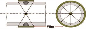
Fig. 6 Single wall, single image (SWSI) or panoramic radiographic technique
Where access to the bore is not possible or the pipe diameter is too small to permit the use of an internal source then the double wall, single image (DWSI) technique is used.
Here the film is placed on the outside of the pipe on the farthest side from the radiographic source, as shown in Fig. 7.
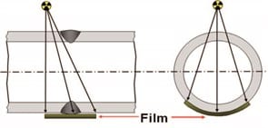
Fig. 7 Double wall, single image
The source may be offset slightly to avoid an image of the upper part of the weld to be projected onto the film or directly in line. The source may be close to or a substantial distance from the pipe, the location being a compromise between a less sharp image but short exposure time for a small stand-off and sharper image but longer exposure time for a large stand-off. The need to penetrate two wall thicknesses means that the sensitivity will be poorer than with the single wall single image technique.
The technique also requires multiple exposures to enable the complete circumference of the pipe to be examined – specification or contract requirements frequently specify the minimum numbers of exposures to ensure complete coverage and images of an acceptable quality. The technique is generally used on pipes over 80mm in diameter.
The last technique is double wall, double image (DWDI), generally used only on pipes less than 75-80mm in diameter.
By offsetting the source from the weld centre line and using a long source to film distance it is possible to project an image onto the film of both the upper and the lower parts of the weld as shown in Fig. 8.
As with the DWSI technique multiple exposures are required to achieve complete coverage.
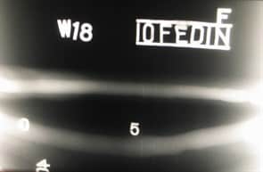
Fig. 8. Double wall double image radiograph of a pipe butt weld. Note the IQI, identification numbers and position markers
This next section will look at some of the more sophisticated radiographic techniques and the advantages and disadvantages of radiography.
The previous information dealt with what may be termed conventional radiographic techniques employing both gamma or X-ray sources and photographic film.
The development of electronics, in particular the increase in computing power over the last 20 or 30 years, has enabled what were laboratory based radiographic methods – real time radiography and computerised tomography (the “CT” scan that is perhaps more familiar in a medical context) -to be implemented both on the shop floor and on site.
The fundamental difference between film radiography and real time radiography is the way in which the radiographic image is handled – the image in real time radiography being produced electronically rather than on film.
This means that the image can be viewed, as the name suggests, in real time – an instant result rather than the significant time delay that occurs when radiographic film is carried to a darkroom, developed and dried before viewing can take place. The real time image is viewed on a monitor screen and the results can be stored and transmitted electronically. An additional difference from film radiography is that the image is a positive rather than the negative image of film radiography, denser materials transmitting less radiation and therefore appearing darker and hence voids, slag entrapment, porosity etc. show as light areas in a welded joint.
Early real time radiographic equipment used a fluorescent screen which interacted with the x-ray radiation to produce an image that was then passed through an image intensifier. This enabled a video film to be produced and the image to be displayed on a monitor screen in real time.
Developments in computing power now enable the image to be digitised and enhanced and then analysed.
Comparison with a set of pre-programmed parameters e.g. an acceptance standard, enable the process of inspection and acceptance/rejection to be automated.
Fluorescent screens to a great extent have been replaced by flat or curved screen photodiode arrays based on Si sensors with other alloys e.g. Pb and Hg, being researched in order to improve further the sensitivity of the examination method. Photo-conductors such as selenium or cadmium telluride are also used in what is termed “direct conversion” to give a sharper image than that from the photo-diode panels.
The X-ray source has been progressively reduced in size such that the focal spot is now as small as 2 or 3 microns and with micro-focus units to as small as 0.1mm, again resulting in improved image quality. These features also enable the image to be enlarged with magnifications of over 1000 times being available with little or no loss in image quality.
Real time radiography is employed in applications where a rapid in-production inspection is required. It has found extensive use in the electronics industry for the in-line examination of circuit boards, in the aerospace and automotive industries for the examination of castings and, often using gamma ray sources, in the process industry for the detection of corrosion. By moving the component between the X-ray source and the detector screen seam welded tube and tube butt welds can be inspected.
Robust, portable manipulating equipment is commercially available for the on-site examination of process pipework and cross country pipelines. Orbiting heads carrying both an X-ray source and, diametrically opposed, the detection screen, are capable of radiographing pipe butt welds with a substantial reduction in time compared with a conventional film radiograph, particularly where multiple exposures are required to give full coverage of the weld. The head rotates around the pipe to give a DWSI (double wall single image) with very high resolution and good contrast.
Internal crawlers equipped with a rotating X-ray head and an external detector can be used to provide a SWSI (single wall single image) radiograph. The examination results are instantly available for display on a laptop screen, the images being stored on disc or memory stick. No film processing or darkroom are required resulting in a further reduction in cost. A typical commercially available unit is illustrated in Fig 9.
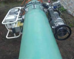
Fig 9. Portable Real Time Radiographic unit for pipeline inspection. (Courtesy Shaw Pipeline Services)
Computed tomography (CT) is a process that uses the techniques of real time radiography to produce three dimensional, rather than two dimensional, images of components. Both the external surfaces and the internal structures of an item can be imaged. All materials – metals, plastics, composites, rocks, fossils, and the human body – can be scanned, making CT scanning a very powerful investigatory and diagnostic tool. Industrial CT scanning is used in many applications for the internal inspection of components, metrology, and for reverse engineering.
The earliest CT units utilised an X-ray beam collimated to create a fan shaped beam of radiation which is scanned across the item, the beam being collected at the detector screen.
The signal is then manipulated by a powerful software programme, enabling a 3D image to be created. The technique was further improved when the fan shaped beam was replaced by a cone shaped beam. Rotating the part beneath the beam enables a sequence of 2D images to be obtained, generally between 360 (one image per degree) to 3,600 images, depending on the desired resolution, with scanning of the object being completed in as little as a few seconds. The images are subsequently combined using complex software to provide a 3D image of the item, the image containing all of the information relating to both the external and internal surfaces of the component. A typical commercially available 225Kv micro-focus unit is shown in Fig. 10.
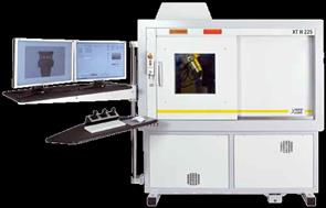
Fig. 10 CT scanning equipment showing control console, viewing screen and radiation proofed cabinet containing the X-ray source, turntable and detector screen. (Courtesy Nikon Metrology UK Ltd)
The 3D image can be manipulated to provide slices through the object and these slices can be rotated so that the precise size and position of internal features can be accurately determined. Assembly or machining errors can be identified. Similarly, flaws within a welded joint or casting can be categorised and the size and position of inclusions, lack of fusion, cracks etc. accurately measured, thus allowing an accurate Engineering Critical Assessment (ECA) to be carried out.
The method can also be used to examine non-metallics – a couple of examples being the inspection of composite wind turbine blades for de-laminations and the positioning of the cores in lost wax casting.
The technique can also be used for accurate measurement of the internal and external surfaces of a component, the image being capable of being overlaid on a CAD drawing of the object. This is particularly useful where parts are provided by a number of suppliers to a manufacturer for subsequent assembly.
The items can be checked against a CAD drawing before dispatch and, if required, the manufacturer instantly provided with the results, thus reducing the risk of being supplied with non-fitting parts. Unfortunately, unlike real time radiography that has moved from being a non-portable method to construction site use, CT scanning requires the use of a protective enclosure containing the X-ray source, the detector screen and a precision turntable. The method is currently therefore confined to within a factory or laboratory environment.
The final radiographic method is neutron radiography. Neutrons, like X- and gamma-radiation, will pass through solid materials and can be used to produce an image on photographic film or to react with a detector screen.
Neutrons, however, unlike X- and gamma radiation, are strongly affected and absorbed by certain elements such as hydrogen, carbon and boron but to a far lesser extent by iron, nickel and aluminium. Neutron radiography is therefore useful in detecting the presence of material containing hydrogen or hydrocarbons – this includes corrosion products, water, explosives, oil and plastics.
Composite items e.g. a combination of metal and plastic, can be non-destructively examined for assembly faults or manufacturing defects; explosive ordnance can be examined for complete filling and fluid flow analysis can be carried out in real time – oil flow in vehicle engines, fluid flow in piping systems.
Neutron radiography can be used with conventional film with real time techniques and for CT scanning. The neutrons are produced by particle accelerators or, with poorer image definition, from certain isotopes, primarily californium252. The method is currently not portable but development work is in progress to address this limitation.
Copyright © TWI Ltd 2014
The content of this article was correct at the time of publication.
For more information visit www.twi-global.com