
Following on from Volume 32, discussed here are another set of defects and imperfections that are common in welds.
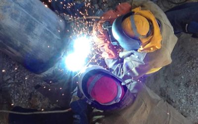
Solidification Cracking
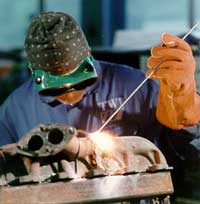
Weld repair on a cast iron exhaust manifold
A crack may be defined as a local discontinuity produced by a fracture which can arise from the stresses generated on cooling or acting on the structure. It is the most serious type of imperfection found in a weld and should be removed. Cracks not only reduce the strength of the weld through the reduction in the cross section thickness but also can readily propagate through stress concentration at the tip, especially under impact loading or during service at low temperature.
Identification
Visual appearance
Solidification cracks are normally readily distinguished from other types of cracks due to the following characteristic factors:
- they occur only in the weld metal
- they normally appear as straight lines along the centreline of the weld bead, as shown in Fig.1, but may occasionally appear as transverse cracking depending on the solidification structure
- solidification cracks in the final crater may have a branching appearance
- as the cracks are often ‘open’, they can be visible to the naked eye

Fig.1 Solidification crack along the centre line of the weld
On breaking open the weld, the crack surface in steel and nickel alloys may have a blue oxidised appearance, showing that they were formed while the weld metal was still hot.
Metallography
The cracks form at the solidification boundaries and are characteristically interdendritic. The morphology reflects the weld solidification structure and there may be evidence of segregation associated with the solidification boundary.
Causes
The overriding cause of solidification cracking is that the weld bead in the final stage of solidification has insufficient strength to withstand the contraction stresses generated as the weld pool solidifies. Factors which increase the risk include:
- insufficient weld bead size or shape
- welding under high restraint
- material properties such as a high impurity content or a relatively large amount of shrinkage on solidification
Joint design can have a significant influence on the level of residual stresses.
Large gaps between component parts will increase the strain on the solidifying weld metal, especially if the depth of penetration is small. Therefore, weld beads with a small depth-to-width ratio, such as formed in bridging a large gap with a wide, thin bead, will be more susceptible to solidification cracking, as shown in Fig.2.
In this case, the centre of the weld which is the last part to solidify, is a narrow zone with negligible cracking resistance.
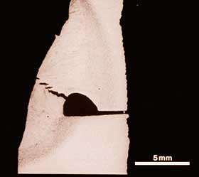
Fig.2 Weld bead penetration too small
Segregation of impurities to the centre of the weld also encourages cracking.
Concentration of impurities ahead of the solidifying weld front forms a liquid film of low freezing point which, on solidification, produces a weak zone.
As solidification proceeds, the zone is likely to crack as the stresses through normal thermal contraction build up. If liquid from the weld pool can feed into an incipient crack, it can be prevented.
For this reason, an elliptically shaped weld pool is preferable to a tear drop shape, and fast welding speeds, which result in a large separation between the weld pool and cracking locations, increase the risk of cracking.
Welding with contaminants such as cutting oils on the surface of the parent metal will also increase the build up of impurities in the weld pool and the risk of cracking.
As the compositions of the plate and the filler determine the weld metal composition they will, therefore, have a substantial influence on the susceptibility of the material to cracking.
Steels
Cracking is associated with impurities, particularly sulphur and phosphorus, and is promoted by carbon whereas manganese and silicon can help to reduce the risk.
To minimise the risk of cracking, fillers with low carbon and impurity levels and a relatively high manganese content are preferred. As a general rule, for carbon-manganese steels, the total sulphur and phosphorus content should be no greater than 0.06%.
Weld metal composition is dominated by the consumable and as the filler is normally cleaner than the metal being welded, cracking is less likely with low dilution processes such as MMA and MIG.
Plate composition assumes greater importance in high dilution situations such as when welding the root in butt welds, using an autogenous welding technique like TIG, or a high dilution process such as submerged arc welding.
In submerged arc welds, as described in EN 1011-2:2001 Annex E, the cracking risk may be assessed by calculating the Units of Crack Susceptibility (UCS) from the weld metal chemical composition (weight %):
UCS = 230C* + 190S + 75P + 45Nb – 12.3Si – 5.4Mn – 1C* = carbon content or 0.08 whichever is higher
Although arbitrary units, a value of <10 indicates high cracking resistance whereas >30 indicates a low resistance.
Within this range, the risk will be higher in a weld run with a high depth to width ratio, made at high welding speeds or where the fit-up is poor. For fillet welds, runs having a depth to width ratio of about one, UCS values of 20 and above will indicate a risk of cracking.
For a butt weld, values of about 25 UCS are critical. If the depth to width ratio is decreased from 1 to 0.8, the allowable UCS is increased by about nine.
However, very low depth to width ratios, such as obtained when penetration into the root is not achieved, also promote cracking.
Aluminium
The high thermal expansion (approximately twice that of steel) and substantial contraction on solidification (typically 5% more than in an equivalent steel weld) means that aluminium alloys are more prone to cracking.
The risk can be reduced by using a crack resistant filler (usually from the 4xxx and 5xxx series alloys) but the disadvantage is that the resulting weld metal is likely to have non-matching properties such as a lower strength than the parent metal.
Austenitic Stainless Steel
A fully austenitic stainless steel weld is more prone to cracking than one containing between 5-10% of ferrite.
The beneficial effect of ferrite has been attributed to its capacity to contain harmful impurities within the grains which would otherwise form low melting point segregates and consequently interdendritic cracks.
Therefore the choice of filler material is important to suppress cracking so a type 308 filler is used to weld type 304 stainless steel.
Best practice in avoiding solidification cracking. Apart from the choice of material and filler, the principal techniques for minimising the risk of welding solidification cracking are:
- Control joint fit-up to reduce gaps.
- Before welding, clean off all contaminants from the material
- Ensure that the welding sequence will not lead to a build-up of thermally induced stresses.
- Select welding parameters and technique to produce a weld bead with an adequate depth to width ratio, or with sufficient throat thickness (fillet weld), to ensure the weld bead has sufficient resistance to the solidification stresses (recommend a depth to width ratio of at least 0.5:1).
- Avoid producing too large a depth to width ratio which will encourage segregation and excessive transverse strains in restrained joints. As a general rule, weld beads whose depth to width ratio exceeds 2:1 will be prone to solidification cracking.
- Avoid high welding speeds (at high current levels) which increase the amount of segregation and the stress level across the weld bead.
- At the run stop, ensure adequate filling of the crater to avoid an unfavourable concave shape.
Acceptance standards
As solidification cracks and crater cracks are linear imperfections with sharp edges, they are not permitted for welds meeting the quality levels B, C and D in accordance with the requirements of BS EN ISO 5817:2007.
Crater pipes may be permitted for quality level D, depending on their size.
Detection and remedial action
Surface breaking solidification cracks can be readily detected using visual examination, liquid penetrant or magnetic particle testing techniques. Internal cracks require ultrasonic or radiographic examination techniques.
Most codes will specify that all cracks should be removed.
A cracked component should be repaired by removing the cracks with a safety margin of approximately 5mm beyond the visible ends of the crack. The excavation is then re-welded using a filler which will not produce a crack sensitive deposit.
Reheat Cracking
Location of reheat cracks in a nuclear pressure vessel steel
The characteristic features and principal causes of reheat cracking are described.
General guidelines on best practice are given so that welders can minimise the risk of reheat cracking in welded fabrications.
Identification
Visual appearance
Reheat cracking may occur in low alloy steels containing alloying additions of chromium and molybdenum or chromium, molybdenum and vanadium when the welded component is being subjected to post weld heat treatment, such as stress relief heat treatment, or has been subjected to high temperature service (typically in the range 350 to 550°C).
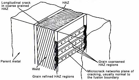
Cracking is almost exclusively found in the coarse grained regions of the heat affected zone (HAZ) beneath the weld, or cladding, and in the coarse grained regions within the weld metal.
The cracks can often be seen visually, usually associated with areas of stress concentration such as the weld toe.
Cracking may be in the form of coarse macro-cracks or colonies of micro-cracks.
A macro-crack will appear as a ‘rough’ crack, often with branching, following the coarse grain region, (Fig. 1a).
Cracking is always intergranular along the prior austenite grain boundaries (Fig. 1b). Macro-cracks in the weld metal can be oriented either longitudinal or transverse to the direction of welding.
Cracks in the HAZ, however, are always parallel to the direction of welding.
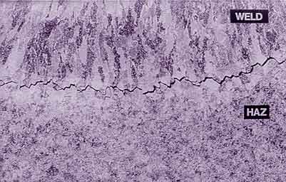
Fig.1a. Cracking associated with the coarse grained heat affected zone
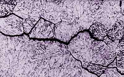
Fig.1b. Intergranular morphology of reheat cracks
Micro-cracking can also be found both in the HAZ and within the weld metal. Micro-cracks in multi-pass welds will be found associated with the grain coarsened regions which have not been refined by subsequent passes.
Causes
The principal cause is that when heat treating susceptible steels, the grain interior becomes strengthened by carbide precipitation, forcing the relaxation of residual stresses by creep deformation at the grain boundaries.
The presence of impurities which segregate to the grain boundaries and promote temper embrittlement, e.g. antimony, arsenic, tin, sulphur and phosphorus, will increase the susceptibility to reheat cracking.
The joint design can increase the risk of cracking. For example, joints likely to contain stress concentration, such as partial penetration welds, are more liable to initiate cracks.
The welding procedure also has an influence. Large weld beads are undesirable, as they produce coarse columnar grains within the weld metal and a coarse grained HAZ which is less likely to be refined by the subsequent pass, and therefore will be more susceptible to reheat cracking.
Best practice in prevention
The risk of reheat cracking can be reduced through the choice of steel, specifying the maximum impurity level and by adopting a more tolerant welding procedure / technique.
Steel choice
If possible, avoid welding steels known to be susceptible to reheat cracking.
For example, A 508 Class 2 is known to be particularly susceptible to reheat cracking, whereas cracking associated with welding and cladding in A508 Class 3 is largely unknown.
The two steels have similar mechanical properties, but A508 Class 3 has a lower Cr content and a higher manganese content.
Similarly, in the higher strength, creep-resistant steels, an approximate ranking of their crack susceptibility is as follows:
| 5 Cr 1Mo | lower risk |
| 2.25Cr 1 Mo | ↓ |
| 0.5Mo B | ↓ |
| 0.5Cr 0.5Mo 0.25V | higher risk |
Thus, in selecting a creep-resistant, chromium molybdenum steel, 0.5Cr 0.5Mo 0.25V steel is known to be susceptible to reheat cracking but the 2.25Cr 1Mo which has a similar creep resistance, is significantly less susceptible.
Unfortunately, although some knowledge has been gained on the susceptibility of certain steels, the risk of cracking cannot be reliably predicted from the chemical composition. Various indices, including ΔG1, PSR and Rs, have been used to indicate the susceptibility of steel to reheat cracking.
Steels which have a value of ΔG1 of less than 2, PSR less than zero or Rs less than 0.03, are less susceptible to reheat cracking.
ΔG1 = 10C + Cr + 3.3Mo + 8.1V – 2
PSR= Cr +Cu + 2Mo + 10V +7Nb + 5Ti – 2
Rs = 0.12Cu +0.19S +0.10As + P +1.18Sn + 1.49Sb
Irrespective of the steel type, it is important to purchase steels specified to have low levels of impurity elements (antimony, arsenic, tin, bismuth, sulphur and phosphorus).
To avoid weld metal reheat cracking, it is necessary to ensure that welding consumables deposit weld metal with appropriately low levels of these impurities, and preferably to avoid coarse columnar grains. Following several instances of weld metal reheat cracking in thick-wall 2.25%Cr-1%Mo-0.25%V reactor vessels, impurities in the flux were identified as being responsible for the cracking, and an equation given for the desired upper limit of these additional impurities.
K = Pb + Bi + 0.03Sb (ppm)
The compositional factor K must be less than 1.5 to achieve freedom from this form of cracking.
Welding procedure and technique
The welding procedure can be used to minimise the risk of reheat cracking by:
- Producing the maximum refinement of the coarse grain HAZ
- Limiting the degree of austenite grain growth
- Eliminating stress concentrations
The procedure should aim to refine the coarse grained HAZ by subsequent passes. In butt welds, maximum refinement can be achieved by using a steep-sided joint preparation with a low angle of attack to minimise penetration into the side-wall, (Fig 2a).
In comparison, a larger angle V preparation produces a wider HAZ, limiting the amount of refinement achieved by subsequent passes, (Fig 2b). Narrow joint preparations, however, are more difficult to weld, due to the increased risk of lack of side-wall fusion.
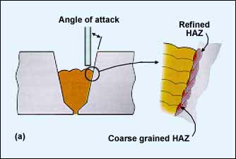
Fig.2a. Welding in the flat position – high degree of HAZ refinement
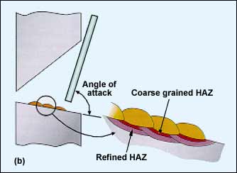
Fig.2b. Welding in the horizontal/vertical position – low degree of HAZ refinement
Refinement of the HAZ can be promoted by first buttering the surface of the susceptible plate with a thin weld metal layer using a small diameter (3.2mm) electrode. The joint is then completed using a larger diameter (4 – 4.8mm) electrode, which is intended to generate sufficient heat to refine any remaining coarse grained HAZ under the buttered layer.
The degree of austenite grain growth can be restricted by using a low heat input. However, precautionary measures may be necessary to avoid the risk of hydrogen-assisted cracking and lack-of-fusion defects. For example, reducing the heat input will almost certainly require a higher preheat temperature to avoid hydrogen-assisted cracking.
The joint design and welding technique adopted should ensure that the weld is free from localised stress concentrations which can arise from the presence of notches. Stress concentrations may be produced in the following situations:
- welding with a backing bar
- a partial penetration weld leaving a root imperfection
- internal weld imperfections such as lack of sidewall fusion
- the weld has a poor surface profile, especially sharp weld toes
The weld toes of the capping pass are particularly vulnerable, as the coarse grained HAZ may not have been refined by subsequent passes. In susceptible steel, the last pass should never be deposited on the parent material, but always on the weld metal, so that it will refine the HAZ.
Grinding the weld toes with the pre-heat maintained has been successfully used to reduce the risk of cracking in 0.5Cr 0.5Mo 0.25V steels.
Hydrogen Cracking in Steels
Hydrogen cracking may also be called cold cracking or delayed cracking.
Preheating to avoid hydrogen cracking
The principal distinguishing feature of this type of crack is that it occurs in ferritic steels, most often immediately on welding or a short time after welding.
In this article, the characteristic features and principal causes of hydrogen cracks are described.
Identification
Visual appearance
Hydrogen cracks can be usually be distinguished due to the following characteristics:
- In C-Mn steels, the crack will normally originate in the heat affected zone (HAZ), but may extend into the weld metal (Fig 1).
- Cracks can also occur in the weld bead, normally transverse to the welding direction at an angle of 45° to the weld surface. They follow a jagged path, but may be non-branching.
- In low alloy steels, the cracks can be transverse to the weld, perpendicular to the weld surface, but are non-branching, and essentially planar.
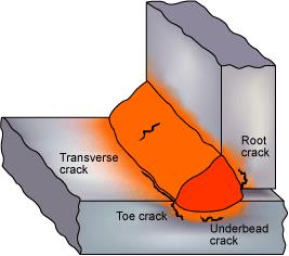
Fig. 1 Hydrogen cracks originating in the HAZ and weld metal. (Note that the type of cracks shown would not be expected to form in the same weldment.)
On breaking open the weld (prior to any heat treatment), the surface of the cracks will normally not be oxidised, even if they are surface breaking, indicating they were formed when the weld was at or near ambient temperature. A slight blue tinge may be seen from the effects of preheating or welding heat.
Metallography
Cracks which originate in the HAZ are usually associated with the coarse grain region, (Fig 2).
The cracks can be intergranular, transgranular or a mixture. Intergranular cracks are more likely to occur in the harder HAZ structures formed in low alloy and high carbon steels. Transgranular cracking is more often found in C-Mn steel structures.
In fillet welds, cracks in the HAZ are usually associated with the weld root and parallel to the weld. In butt welds, the HAZ cracks are normally oriented parallel to the weld bead.
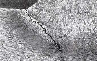
Fig. 2 Crack along the coarse grain structure in the HAZ
Causes
There are three factors which combine to cause cracking:
- hydrogen generated by the welding process
- a hard brittle structure which is susceptible to cracking
- tensile stresses acting on the welded joint
Cracking usually occurs at temperatures at or near normal ambient. It is caused by the diffusion of hydrogen to the highly stressed, hardened part of the weldment.
In C-Mn steels, because there is a greater risk of forming a brittle microstructure in the HAZ, most of the hydrogen cracks are to be found in the parent metal. With the correct choice of electrodes, the weld metal will have a lower carbon content than the parent metal and, hence, a lower carbon equivalent (CE).
However, transverse weld metal cracks can occur, especially when welding thick section components; the risk of cracking is increased if the weld metal carbon content exceeds that of the parent steel.
In low alloy steels, as the weld metal structure is more susceptible than the HAZ, cracking may be found in the weld bead.
The main factors which influence the risk of cracking are:
- weld metal hydrogen
- parent material composition
- parent material thickness
- stresses acting on the weld during welding or imposed (shortly) after welding
- heat input
Weld metal hydrogen content
The principal source of hydrogen is moisture contained in the flux, i.e. the coating of MMA electrodes, the flux in cored wires and the flux used in submerged arc welding. The amount of hydrogen generated is influenced by the electrode type. Basic electrodes normally generate less hydrogen than rutile and cellulosic electrodes.
It is important to note that there can be other significant sources of hydrogen, e.g. from the material, where processing or service history has left the steel with a significant level of hydrogen or moisture from the atmosphere. Hydrogen may also be derived from the surface of the material or the consumable.
Sources of hydrogen will include:
- oil, grease and dirt
- rust
- paint and coatings
- cleaning fluids
Parent metal composition
This will have a major influence on hardenability and, with high cooling rates, the risk of forming a hard brittle structure in the HAZ. The hardenability of a material is usually expressed in terms of its carbon content or, when other elements are taken into account, its carbon equivalent (CE) value.
The higher the CE value, the greater the risk of hydrogen cracking. Generally, steels with a CE value of <0.4 are not susceptible to HAZ hydrogen cracking, as long as low hydrogen welding consumables or processes are used.
Parent material thickness
Material thickness will influence the cooling rate and therefore the hardness level, the microstructure produced in the HAZ and the level of hydrogen retained in the weld.
The ‘combined thickness’ of the joint, ie the sum of the thicknesses of material meeting at the joint line, will determine, together with the joint geometry, the cooling rate of the HAZ and its hardness.
Consequently, as shown in Fig. 3, a fillet weld is likely to have a greater risk than a butt weld in the same material thickness.
Fig.3 Combined thickness measurements for butt and fillet joints
Stresses acting on the weld
Cracks are more likely to initiate at regions of stress concentration, particularly at the toe and root of the weld.
The stresses generated across the welded joint as it contracts will be greatly influenced by external restraint, material thickness, and joint geometry and fit-up.
Poor fit-up (excessive root gap) in fillet welds markedly increases the risk of cracking. The degree of restraint acting on a joint will generally increase as welding progresses, due to the increase in stiffness of the fabrication.
Heat input
The heat input to the material from the welding process, together with the material thickness and preheat temperature, will determine the thermal cycle and the resulting microstructure and hardness of both the HAZ and the weld metal.
Increasing the heat input will reduce the hardness level, and therefore reduce the risk of HAZ cracking. However, as the diffusion distance for the escape of hydrogen from a weld bead increases with increasing heat input, the risk of weld metal cracking is increased.
Heat input per unit length is calculated by multiplying the arc energy by a thermal efficiency factor, according to the following formula:
![]()
- V = arc voltage (V)
- A = welding current (A)
- S = welding speed (mm/min)
- k = thermal efficiency factor
In calculating heat input, the thermal efficiency must be taken into consideration. The thermal efficiency factors given in EN 1011-1: 2009 for the principal arc welding processes, are:
| Submerged arc (single wire) |
1.0 |
| MMA | 0.8 |
| MIG/MAG and flux cored wire | 0.8 |
| TIG and plasma | 0.6 |
In MMA welding, heat input is normally controlled by means of the run-out length from each electrode, which is proportional to the heat input.
As the run-out length is the length of weld deposited from one electrode, it will depend upon the welding technique, e.g. weave width /dwell.
Prevention and Best Practice
Techniques and practical guidance on the avoidance of hydrogen cracks are described:
- Preheating
- Interpass and post weld heating to prevent hydrogen cracking
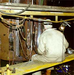
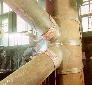
Preheating of a jacket structure to prevent hydrogen cracking
There are three factors which combine to cause hydrogen cracking in arc welding:
- hydrogen generated by the welding process
- a hard brittle structure which is susceptible to cracking
- tensile stresses acting on the welded joint
Cracking generally occurs when the temperature has reached normal ambient.
In practice, for a given situation (material composition, material thickness, joint type, electrode composition and heat input), the risk of hydrogen cracking is reduced by heating the joint.
Preheat
Preheat, which slows the cooling rate, allows some hydrogen to diffuse away, and generally reduces the hardness, and therefore susceptibility to cracking, of hard, crack-sensitive microstructural regions.
The recommended levels of preheat for carbon and carbon manganese steel are detailed in EN 1011-2: 2001 (which incorporates nomograms derived from those in BS 5135: 1984).
The preheat level may be as high as 200°C for example, when welding thick section steels with a high carbon equivalent (IIW CE) value.
Interpass and post-heating
As cracking rarely occurs at temperatures above ambient, maintaining the temperature of the weldment during fabrication is equally important.
For susceptible steels, it is usually appropriate to maintain the preheat temperature for a given period, typically between two to three hours, to enable the hydrogen to diffuse away from the weld area.
In crack-sensitive situations, such as welding higher IIW CE steels or under high restraint conditions, the temperature and heating period should be increased, typically 250-300°C for three to four hours.
For many steels, post-weld heat treatment (PWHT) may be used immediately on completion of welding, i.e. without allowing the preheat temperature to fall.
However, in practice, as inspection can only be carried out at ambient temperature, there is the risk that ‘rejectable’ defects will only be found after PWHT. Also, for highly hardenable steels, a second heat treatment may be required to temper the hard microstructure present after the first PWHT.
Under certain conditions, more stringent procedures (with a higher preheat temperature and/or a lower weld metal hydrogen level) are needed to avoid cracking than those derived from the nomograms for estimating preheat in Fig. C2 of EN 1011-2. Section C.2.9 of this standard mentions the following conditions:
- High restraint, including welds in section thicknesses above approximately 50mm, and root runs in double bevel joints
- Thick sections (≥ approximately 50mm)
- Low carbon equivalent steels (C-Mn steels with C ≤ 0.1% and IIW CE ≤ approximately 0.42)
- ‘Clean’ or low sulphur steels (S ≤ approximately 0.008%), as a low sulphur and low oxygen content will increase the hardenability of a steel.
- Alloyed weld metal where preheat levels to avoid HAZ cracking may be insufficient to protect the weld metal. Low hydrogen processes and consumables should be used.
- Schemes for predicting the preheat requirements to avoid weld metal cracking generally require the weld metal diffusible hydrogen level and the weld metal tensile strength as input.
Use of austenitic and nickel alloy weld metal to prevent cracking
In situations where preheating is impractical, or does not prevent cracking, it will be necessary to use an austenitic consumable.
Austenitic stainless steel and nickel alloy electrodes will produce a weld metal which at ambient temperature has a higher solubility for hydrogen than ferritic steel. Thus, any hydrogen formed during welding becomes locked in the weld metal, with very little diffusing to the HAZ on cooling to ambient temperature.
A commonly used austenitic MMA electrode is 23Cr:12Ni, e.g. from EN 1600: 1997. However, as nickel alloys have a lower coefficient of thermal expansion than stainless steel, nickel alloy electrodes are preferred, to reduce the shrinkage strain, when welding highly restrained joints. Figure 1 is a general guide on the levels of preheat when using austenitic electrodes.
When welding steels with up to 0.2%C, a preheat would not normally be required. However, above 0.4%C a minimum temperature of 150°C will be needed to prevent HAZ cracking. The influence of hydrogen level and the degree of restraint are also illustrated in the figure.
Fig.1 Guide to preheat temperature when using austenitic MMA electrodes at 1-2kJ/mm a) low restraint (e.g. material thickness <30mm) b) high restraint (e.g. material thickness >30mm)
Best practice in avoiding hydrogen cracking
Reduction in weld metal hydrogen
The most effective means of avoiding hydrogen cracking is to reduce the amount of hydrogen generated by the consumable, ie by using a low hydrogen process or low hydrogen electrodes.
Welding processes can be classified as high, medium, low, very low and ultra-low, depending on the amount of weld metal hydrogen produced in a standard test block.
The weld metal diffusible hydrogen levels (ml/100g of deposited metal, measured in a test weld, as specified in BS EN ISO 3690:2001), and the hydrogen scale designations of EN 1011-2: 2001 are as follows:
| High | >15 | Scale A |
| Medium | >10 <15 | Scale B |
| Low | >5 <10 | Scale C |
| Very low | >3 <5 | Scale D |
| Ultra-low | ≤3 | Scale E |
Figure 2 from Bailey et al illustrates the relative amounts of weld metal hydrogen produced by the major welding processes. MMA, in particular, has the potential to generate a wide range of hydrogen levels.
Thus, to achieve the lower values, it is essential that basic electrodes are used, and they are baked in accordance with the manufacturer’s recommendations, or taken from special packaging immediately before use, and exposed to ambient conditions for no longer than the time period specified by the manufacturer.
For the MIG process, cleaner wires will be required to achieve very low hydrogen levels.
Fig.2 General relationships between potential hydrogen and weld metal hydrogen levels for arc welding processes
General guidelines
The following general guidelines are recommended for the various types of steel, but requirements for specific steels should be checked according to EN 1011-2: 2001
Mild steel (CE <0.4)
- readily weldable, preheat generally not required if low hydrogen processes or electrodes are used
- preheat may be required when welding thick section material, high restraint and with higher levels of hydrogen being generated
C-Mn, medium carbon, low alloy steels (CE 0.4 to 0.5)
- thin sections can be welded without preheat, but thicker sections will require low preheat levels, and low hydrogen processes or electrodes should be used
Higher carbon and alloyed steels (CE >0.5)
- preheat, low hydrogen processes or electrodes, post-weld heating and slow cooling required.
More detailed guidance on the avoidance of hydrogen cracking is described in EN 1011-2: 2001.
Practical Techniques
The following practical techniques are recommended to avoid hydrogen cracking:
- clean the joint faces and remove contaminants such as paint, cutting oils, grease
- use a low hydrogen process, if possible
- bake the electrodes (MMA) or the flux (submerged arc) and then either store them warm or restrict the duration of exposure to ambient conditions, all in accordance with the manufacturer’s recommendations
- reduce stresses on the weld by avoiding large root gaps and high restraint
- if preheating is specified in the welding procedure, it should also be applied when tacking or using temporary attachments
- preheat the joint to a distance of at least 75mm from the joint line, ensuring uniform heating through the thickness of the material
- measure the preheat temperature on the face opposite that being heated. Where this is impractical, allow time for the equalisation of temperature after removing the preheating before the temperature is measured
- adhere to the preheat and minimum interpass temperature, and heat input requirements
- maintain heat for approximately two to four hours after welding, depending on crack sensitivity
- In situations where adequate preheating is impracticable, or cracking cannot be avoided, austenitic electrodes may be used
Acceptance standards
As hydrogen cracks are linear imperfections which have sharp edges, they are not permitted for welds meeting the quality levels B, C and D in accordance with the requirements of EN ISO 5817.
Detection and remedial action
As hydrogen cracks are often very fine and may be sub-surface, they can be difficult to detect. Surface-breaking hydrogen cracks can be readily detected using visual examination, liquid penetrant or magnetic particle testing techniques.
Internal cracks require ultrasonic or radiographic examination techniques.
Ultrasonic examination is preferred, as radiography is restricted to detecting relatively wide cracks that are parallel to the beam.
As the formation of cracks may be delayed for many hours after completion of welding, the delay time before inspection, according to the relevant fabrication code, should be observed.
Most codes will specify that all cracks should be removed. A cracked component should be repaired by removing the cracks with a safety margin of approximately 5mm beyond the visible ends of the crack. The excavation is then re-welded.
To make sure that cracking does not re-occur, welding should be carried out with the correct procedure, i.e. preheat and an adequate heat input level for the material type and thickness.
However, as the level of restraint will be greater and the interpass time shorter when welding within an excavation compared to welding the original joint, it is recommended that a higher level of preheat is used (typically by 50°C).
Copyright © TWI Ltd 2014
The content of this article was correct at the time of publication. For more information visit www.twi-global.com