Information and Guidance to FCAW
Flux core arc welding (FCAW) was introduced in the 1950’s as an alternative to shielded metal arc welding (SMAW). The advantage of FCAW over SMAW is that the use of the stick electrodes used in SMAW is unnecessary. This helped FCAW to overcome many of the restrictions associated with SMAW. Technically the introduction of this process was not new. It was just a new type of an electrode that can be used on a GMAW welding machine. Flux cored arc welding is a process similar to GMAW welding. Both processes using continues wire feeds, and similar equipment. The power supply for a FCAW, and a GMAW welder, are the same machine. They are both considered semi automatic processes, and have a very high production rate.
Flux-cored arc welding (FCAW or FCA) is a semi-automatic or automatic arc welding process. FCAW requires a continuously-fed consumable tubular electrode containing a flux and a constant-voltage or, less commonly, a constant-current welding power supply. An externally supplied shielding gas is sometimes used, but often the flux itself is relied upon to generate the necessary protection from the atmosphere, producing both gaseous protection and liquid slag protecting the weld. The process is widely used in construction because of its high welding speed and portability and its ability to be used in field conditions. The main difference between flux cored arc welding and GMAW welding is the way the electrode is shielded from the air. Flux cored arc welding just like the name implies, has a hollow wire with flux in the centre, just as the name states, a ‘Flux Core’.
Types
One type of FCAW requires no shielding gas. This is made possible by the flux core in the tubular consumable electrode. However, this core contains more than just flux, it also contains various ingredients that when exposed to the high temperatures of welding generate a shielding gas for protecting the arc. This type of FCAW is attractive because it is portable and generally has good penetration into the base metal. Also, windy conditions need not be considered. Some disadvantages are that this process can produce excessive, noxious smoke (making it difficult to see the weld pool).
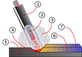
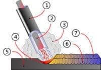
FCAW Electrode cutaway image. 1. Metal electrode sheath 2. Flux core 3. Shielding gas produced by the flux 4. Weld pool, 5. Workpiece 6. Weld metal 7. Flux covering
Another type of FCAW uses a shielding gas that must be supplied by an external supply. This is known informally as “dual shield” welding. This type of FCAW was developed primarily for welding structural steels. In fact, since it uses both a flux-cored electrode and an external shielding gas it is a combination of gas metal (GMAW) and flux-cored arc welding (FCAW). This particular style of FCAW is preferable for welding thicker and out-of-position metals. The slag created by the flux is also easy to remove. The main advantages of this process is that in a closed shop environment, it generally produces welds of better and more consistent mechanical properties, with fewer weld defects than either the SMAW or GMAW processes. In practice it also allows a higher production rate, since the operator does not need to stop periodically to fetch a new electrode, as is the case in SMAW.
However, like GMAW, it cannot be used in a windy environment as the loss of the shielding gas from air flow will produce porosity in the weld.
As with all welding processes, the proper electrode must be chosen to obtain the required mechanical properties. Operator skill is a major factor as improper electrode manipulation or machine setup can cause porosity.
FCAW v GMAW Comparison
FCAW is the most productive of the manual welding processes. A GMAW welder can typically produce 2 – 3.6kgs of weld per hour, versus a FCAW welder who should be able to lay down 10kg of weld per hour. On top of that flux core welding can weld 12mm plates in a single pass with full penetration on both sides. FCAW is primarily used in the haevy fabrication and shipbuilding industries.
Process variables
- Wire feed speed (and current)
- Arc voltage
- Electrode extension
- Travel speed and angle
- Electrode angles and wire type
- Shielding gas composition (if required)
- Reverse polarity (Electrode Positive) is used for FCAW Gas-Shielded wire, Straight polarity (Electrode Negative) is used for self shielded FCAW
Advantages and applications
- FCAW may be an “all-position” process with the right filler metals (the consumable electrode)
- No shielding gas needed with some wires making it suitable for outdoor welding and/or windy conditions
- A high-deposition rate process (speed at which the filler metal is applied) in the 1G/1F/2F
- Some “high-speed” (e.g., automotive) applications
- As compared to SMAW and GTAW, there is less skill required for operators.
- Less pre-cleaning of metal required
- Metallurgical benefits from the flux such as the weld metal being protected initially from external factors until the slag is chipped away
- Porosity chances very low
Used on the following alloys:
- Mild and low alloy steels
- Stainless steels and some high nickel alloys
- Some wearfacing/surfacing alloys
Disadvantages
Of course, all of the usual issues that occur in welding can occur in FCAW such as incomplete fusion between base metals, slag inclusion (non-metallic inclusions), and cracks in the welds. But there are a few concerns that come up with FCAW that are worth taking special note of:
- Melted contact tip – when the contact tip actually contacts the base metal, fusing the two and melting the hole on the end
- Irregular wire feed – typically a mechanical problem
- Porosity – the gases (specifically those from the flux-core) don’t escape the welded area before the metal hardens, leaving holes in the welded metal
- More costly filler material/wire as compared to GMAW
- The equipment is less mobile and more costly as compared to SMAW or GTAW.
- The amount of smoke generated can far exceed that of SMAW, GMAW, or GTAW.
- Changing filler metals requires changing an entire spool. This can be slow and difficult as compared to changing filler metal for SMAW or GTAW.
- Creates more fumes than SMAW.
FCAW Self-Shielding vs Dual Shield
FCAW comes in two types of shielding. The first difference is in the electrode itself, it is a tubular wire with a shielding powder in the centre. In technical terms this is called Self-Shielding or sometimes branded Inner Shield.
Dual Shield requires a gas cover in addition to the flux core shielding. In the case of dual shielding, you have a powder flux in the centre of the electrode and an external shielding gas protecting the weld area.
FCAW Voltage Type – Welding Polarity – Power Supply
FCAW and GMAW use the same power supply i.e. Constant Voltage, as a result, any change in arc length (which is directly related to voltage) results in a large change in heat input and current. Constant voltage power supplies keep the voltage near, or at the same level. Changes to the amperage required for welding is achieved via the wire feed speed. The faster the wire feeds, the more contact the electrode has, producing more amperage, and heat.
Voltage type for FCAW is D/C direct current like the type current produced by a battery. The polarity used in industrial FCAW is typically D/C electrode (+) positive. When welding with smaller electrodes and sheet metals, the polarity is changed to D/C electrode (-) negative.
Shielding Gases for FCAW
In the case of dual shielding being used with a flux cored electrode the choices of shielding gasses are limited.
The choices are as follows:
- CO2 – Carbon dioxide
- Ar – Argon
- CO2 / Ar – A mixture of the two
- Ar / O2 – A mixture of the two
CO2 by itself produces the deepest penetrating weld but has some limitations:
- Mechanical properties of the weld are not the highest achievable
- Potentially a lot of spatter can be produced
- The can suffer instability.
Argon gas is also used with FCAW, but can have similar issues as with CO2. A mixture of Ar with CO2 can result in a good quality weld. The most popular is 25% CO2 with 75% Ar. This shield gas produces a stable arc, with less spatter, and allows more of a spray transfer mode for the electrode.
Another commonly used mixture is Ar / O2 . Oxygen in small percentages stabilises the weld arc and improves the mechanical properties of the weld.
Ultimately if using dual shield, it is always good practice to follow the electrode manufactures recommendations for electrode/gas combinations.
FCAW Electrode Types
FCAW come in standard sizes. Some are the same size as most GMAW welding wire but others are comparable to the thickness of a stick welding electrode. Here are some of the more popular sizes for standard industrial applications:
- 9
- 2
- 6
As with most electrodes there is a standard classification code or designation code, on the spool they come on. To understand the classifications better it is important to know some basics about where the classification codes are different.
A somewhat common flux cored welding electrode is the E71T – 1. As with all electrodes the numbers and letters all mean something. There identifications are as follows.
- E – Stands for electrode.
- 7 – Stands for the minimum amount of tensile strength. In this case it is 70,000 lbs of tensile strength per square inch of weld. The way this number is figured is by adding four zeros to the number.
- 1– Stands for the position that this electrode can be welded in. There are only two designations and they are “0” for flat and horizontal welding, then there is “1” for all position welding.
- T – Stands for a tubular electrode. When “T” is used it is always assumed it is a flux cored electrode.
- 1 – The last is the shielding flux type designations.
As a note, with all flux cored electrodes they need to be stored in accordance with the manufacturers instructions, otherwise they may pick up moisture and this will cause major weld defects.
Flux Cored Welding Transfer Types
There are two metal transfer types used. The transfer types are Spray Transfer and Globular. Spray transfer is the most commonly used. What separates the two transfer types are, voltage settings, wire speed, and the gasses used, if any.
Flux Cored Arc Welding Joint preparation
Joint preparation for flux core is not as critical as with GMAW welding. FCAW can typically burn through mill scale and minor rust. In many cases when the metal is cut with a torch, it can be welded as-is, with no additional cleaning. For the shipbuilding industry this is a huge savings in labour cost. In addition to easy joint preparation, bevelled V-joints can be narrower for metals of 12mm or thinner, and they can be welded in a single pass with full penetration on both sides.
Ceramic Backing Tape
Commonly in many industries, joints are welded from a single side using a ceramic backing tape. When ceramic 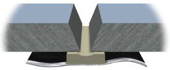 backing tape is used it allows for full joint preparation and outstanding weld quality. This in return gives full control of the shape and penetration of the root side of the weld. Once the weld is finished, the ceramic tape is simply peeled off, and thrown away.
FCAW Machine Set-Up
The basics machine set-up ofr FCAW are the same as GMAW welding. The voltage setting controls the voltage and when choosing them it is best to use the electrodes manufactures voltage recommendations. When choosing a voltage range there are two factors that determine it, electrode size, and metal thickness.
The wire feed speed setting the amperage and therefore the transfer type. The faster the wire feeds to the joint, the more contact the wire has, and that increases the amperage. When using FCAW in the overhead (4G/4F) position, the wire speed should be set to allow for spray transfer
There is sometimes a third setting required for FCAW with a dual shield electrode. Gas flow rate for the shielding gas, which can vary and is dependent on the wire size used, nozzle size, and prevailing wind conditions.
If a GMAW machine is to be used for FCAW, the drive rollers will need to be changed to the correct size. This is important, otherwise the tubular wire could get crushed in the rollers and cause problems in the weld. Tension settings on the rollers should also not be too tight. .
When setting the tension of the rollers they should be loose enough that it is easy for the rollers to slip when the wire is stopped, but should be tight enough to keep the wire feeding to the torch contact tip without disruption to the wire speed. Currect feeding of the wire will give greater arc stability.
FCAW Welding Techniques
Before trying to weld with the FCAW electrode, you will need to determine designation on the label. FCAW electrodes come with two position designations. First is 0 and is used for flat and horizontal welding ONLY. The second designation is 1, which is for all position welding.
FCAW is very similar to GMAW welding when it comes to welding techniques and can be used in either backhand or forehand directions and either technique can be used for any position.
Backhand technique is common for FCAW in the flat (1G/1F) and horizontal positions (2G/2F). The only other time you may want to consider the backhand technique is when welding in the 4G position. The down side of backhand welding is that the weld pool is a little harder to see.
The forehand method is typically used on thinner metals, in the vertical up (3G/3F), and for overhead fillet welds (4F). The forehand method also works well in the flat (1G/1F) and horizontal positions (2G/2F) and allows a greater sight of both the weld pool and weld joint. The downside of this technique is spatter can sometimes become excessive if the travel angle is not right.
FCAW requires a greater electrode extension or ‘stick-out’ than compared to GMAW. Typically, GMAW requires the electrode extension to be 15-20mm. FCAW with a self-shielded electrode, the extension should be kept between 20-25mm, depending on the type, and size of the electrode. In many cases the extra electrode stick-out pre-heats the electrode, which can assist in drying the flux and can prevent any moisture the flux may have absorbed in storage, from contaminating the weld.
Dual shield FCAW, should apply an electrode extension of approximately 15-20mm or less in the majority of welding situations.
Most FCAW electrodes are typically designed for stringer beads.