Submerged Arc Welding
The first patent on the submerged-arc welding (SAW) process was taken out in 1935 and covered an electric arc beneath a bed of granulated flux. Developed by the E O Paton Electric Welding Institute, Russia, during the Second World War, SAW’s most famous application was on the T34 tank.
Process features
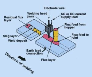
Similar to MIG welding, SAW involves formation of an arc between a continuously-fed bare wire electrode and the workpiece. The process uses a flux to generate protective gases and slag, and to add alloying elements to the weld pool. A shielding gas is not required. Prior to welding, a thin layer of flux powder is placed on the workpiece surface. The arc moves along the joint line and as it does so, excess flux is recycled via a hopper. Remaining fused slag layers can be easily removed after welding. As the arc is completely covered by the flux layer, heat loss is extremely low.
This produces a thermal efficiency as high as 60% (compared with 25% for manual metal arc). There is no visible arc light, welding is spatter-free and there is no need for fume extraction.
Operating characteristics
SAW is usually operated as a fully-mechanised or automatic process, but it can be semi-automatic. Welding parameters: current, arc voltage and travel speed all affect bead shape, depth of penetration and chemical composition of the deposited weld metal. Because the operator cannot see the weld pool, greater reliance must be placed on parameter settings.
Process variants
According to material thickness, joint type and size of component, varying the following can increase deposition rate and improve bead shape.
Wire
SAW is normally operated with a single wire on either AC or DC current. Common variants are:
- Twin wire
- Multiple wire (tandem or triple)
- Single wire with hot or cold wire addition
- Metal powder addition
- Tubular wire
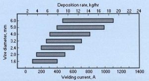
All contribute to improved productivity through a marked increase in weld metal deposition rates and/or travel speeds.
A narrow gap process variant is also established, which utilises a two or three bead per layer deposition technique.
Flux
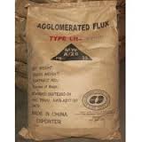
Fluxes used in SAW are granular fusible minerals containing oxides of manganese, silicon, titanium, aluminium, calcium, zirconium, magnesium and other compounds such as calcium fluoride.
The flux is specially formulated to be compatible with a given electrode wire type so that the combination of flux and wire yields desired mechanical properties.
All fluxes react with the weld pool to produce the weld metal chemical composition and mechanical properties.
It is common practice to refer to fluxes as ‘active’ if they add manganese and silicon to the weld, the amount of manganese and silicon added is influenced by the arc voltage and the welding current level.
The main types of flux for SAW are:
Bonded fluxes
Produced by drying the ingredients, then bonding them with a low melting point compound such as a sodium silicate.
Most bonded fluxes contain metallic deoxidisers which help to prevent weld porosity. These fluxes are effective over rust and mill scale.
Fused fluxes
Produced by mixing the ingredients, then melting them in an electric furnace to form a chemically homogeneous product, cooled and ground to the required particle size.
Smooth stable arcs, with welding currents up to 2000A and consistent weld metal properties, are the main attraction of these fluxes.
Applications
SAW is ideally suited for longitudinal and circumferential butt and fillet welds.
However, because of high fluidity of the weld pool, molten slag and loose flux layer, welding is generally carried out on butt joints in the flat position and fillet joints in both the flat and horizontal-vertical positions.
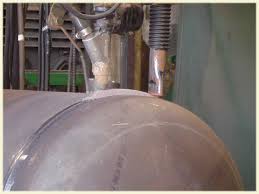
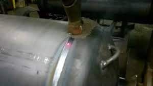
For circumferential joints, the workpiece is rotated under a fixed welding head with welding taking place in the flat position. Depending on material thickness, either single-pass, two-pass or multi-pass weld procedures can be carried out. There is virtually no restriction on the material thickness, provided a suitable joint preparation is adopted.
Most commonly welded materials are carbon-manganese steels, low alloy steels and stainless steels, although the process is capable of welding some non-ferrous materials with judicious choice of electrode filler wire and flux combinations.
What are the common causes of porosity in Submerged Arc welds?
Porosity is a fairly common defect which can be influenced by many factors.
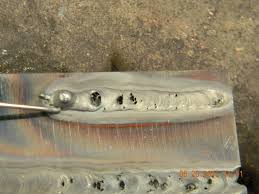
Sometimes it is clearly visible as pinholes in the weld surface, at other times it is below the surface and is revealed only by X-ray examination or ultrasonic testing.
Unless it is gross or preferentially aligned, porosity is unlikely to be harmful.
Common causes of porosity are:
- Contamination of joint surfaces with oil, paint, grease, hydrated oxides, etc. These decompose in the arc to give gaseous products which can cause elongated ‘wormhole’ porosity often located along the centreline of the weld.
2. Damp flux: flux should be kept dry. It is good practice to dry all fluxes before use and store them in a heated hopper. The manufacturer’s recommendations regarding drying temperatures should be observed. Note that if a flux recovery unit, driven by compressed air, is used the compressed air should be dried thoroughly
3. Insufficient flux burden can expose the arc and molten weld pool to atmospheric contamination.
The surface of a weld may sometimes contain small depressions known as surface pocking or gas flats. These are harmless and while the exact cause is not fully understood it is linked to conditions which cause generation of gas or make it difficult for gas to escape; for example, moisture or lack of DE oxidants and too many fines in the flux to allow gas to pass readily.
Advantages
The major advantages of the SAW or submerged arc welding process are:
High quality metal weld
- Extremely high speed and deposition rate
- Smooth, uniform finished weld with no spatter
- Little or no welding fume
- No arc flash, thus minimal need for protective clothing
- High utilisation of electrode wire
- Easy automation for high-operator factor
- Normally, no involvement of manipulative skills
Major Uses
The submerged arc process is widely used in heavy steel plate fabrication work. This includes the welding of structural shapes, the longitudinal seam of larger diameter pipe, the manufacture of machine components for all types of heavy industry, and the manufacture of vessels and tanks for pressure and storage use.
It is widely used in the shipbuilding industry for splicing and fabricating sub-assemblies, and by many other industries where steels are used in medium to heavy thicknesses. It is also used for surfacing and build-up work, maintenance, and repair.
Process Limitations
A major limitation of SAW is its limitation of welding positions. The other limitation is that it is primarily used only to weld mild and low-alloy high-strength steels.
The high-heat input and slow-cooling cycle can be a problem when welding quenched and tempered steels. The heat input limitation of the steel in question must be strictly adhered to when using submerged arc welding.
This may require the making of multi-pass welds where a single pass weld would be acceptable in mild steel. In some cases, the economic advantages may be reduced to the point where flux-cored arc welding or some other process should be considered.
In semiautomatic submerged arc welding, the inability to see the arc and puddle can be a disadvantage in reaching the root of a groove weld and properly filling or sizing.
Metal thicknesses from 1.6 to 12.7 mm can be welded with no edge preparation. With edge preparation, welds can be made with a single pass on material from 6.4 to 25.4 mm.
When a multipass technique is used, the maximum thickness is practically unlimited. Horizontal fillet welds can be made up to 9.5 mm in a single pass and in the flat position, fillet welds can be made up to 25 mm size.
Joint Design
Although the submerged arc welding process can utilize the same joint design details as the shielded metal arc welding process, different joint details are suggested for maximum utilization and efficiency of submerged arc welding. For groove welds, the square groove design can be used up to 16 mm thickness. Beyond this thickness, bevels are required. Open roots are used but backing bars are necessary since the molten metal will run through the joint.
When welding thicker metal, if a sufficiently large root face is used, the backing bar may be eliminated. However, to assure full penetration when welding from one side, backing bars are recommended. Where both sides are accessible, a backing weld can be made which will fuse into the original weld to provide full penetration.
Copyright © TWI Ltd 2014
The content of this article was correct at the time of publication. For more information visit www.twi-global.com


